
Load pull analysis solutions
Nonlinear device characterization for active components
Active devices, such as power amplifiers (PA), are not inherently 50 Ohm components. They are designed to operate in an environment where the characteristic impedance is nominally 50 Ohms, but in reality, the impedance can vary widely. In other words, while the environment they are meant to operate in is typically standardized to 50 Ohms, the actual impedance seen by the amplifier can deviate from this value.
In order to achieve specific target specifications, such as minimizing power consumption or optimizing modulation performance, it is crucial to optimize the matching of components with the surrounding environment. This requires a test environment with variable impedances, as the performance of active devices can vary significantly depending on the impedances they are interfaced with in the target design. Load pull analysis is key to determining the optimal operating conditions, or “sweet spot,” for the final design.
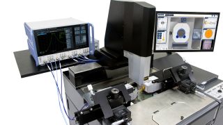
Rohde & Schwarz is working with leading load pull companies to offer complete turnkey solutions for passive, active and hybrid load pull systems. Measurements can be conducted traditionally or via probing systems, depending on the accessibility of the device under test (DUT).
Your load pull testing challenges
Load pull measurements are applied in various test scenarios, and each comes with its own challenges. The scenarios can be divided into two categories: design optimization and modeling.
Design optimization challenges:
- Understanding the characteristics of different key performance indicators (KPI) across different impedances: The performance is typically shown in contour plots across the Smith chart for different impedances. This information allows various target figures, such as maximum output power, lowest intermodulation or best energy efficiency, to be optimized. Unfortunately, the sweet spot for the different KPIs typically require different loads, so trade-offs must often be made to optimize for the target application.
- Impedance optimization at second and third harmonic frequencies: Both impedance tuning at the fundamental frequency and impedance optimization at the second and third harmonic frequencies are required for best efficiency. This is especially true for higher power applications.
- Designing matching networks for PA transistors: This requires knowledge of the inherent device impedance at the input and output. Source pull at the input and load pull on the output help to identify the correct values.
- Verifying system level performance with different impedances at the RF frontend: This is done with a load pull measurement setup and often includes modulated performance verification with load pull testing. At the system level, when the radio frequency (RF) PA is connected to an antenna for wireless communication covering multiple frequency bands, the PA needs to handle the impedance variation of the antenna over the total used frequency range.
In modeling, the main challenge is creating reliable PA transistor models, as used in system-level simulation. For this, the transistors’ behavior must be described across many working conditions (e.g., frequency and level range), device settings (e.g., biasing) and different impedances on the input and output. Load pull analysis is typically used to get this information.
High-performance solutions for load pull testing
Load pull relies on the flexible variation of the impedance presented to the DUT, such as an RF power amplifier. This can be applied to the output as load pull or to the input as source pull, and the techniques remain the same. Load pull can be categorized based on approach and application:
- Passive load pull
- Active load pull
- Hybrid load pull
- Harmonic load pull
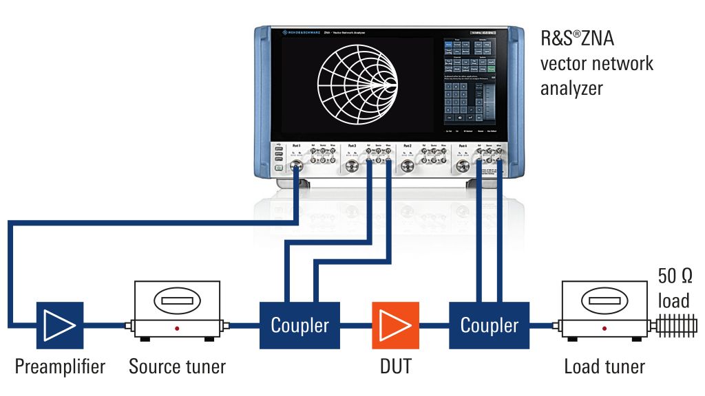
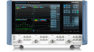
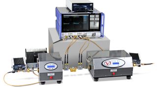
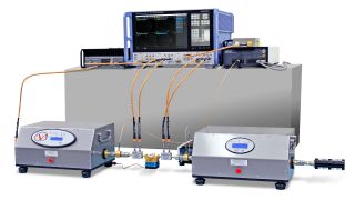
Passive load pull is the traditional approach that uses mechanical impedance tuners on the input for source pull and/or output for load pull. It is placed between the DUT and the test instrumentation. For the tuners, we work with our solution partners Focus Microwaves and Maury Microwave. For the main test instrument, we recommend the flexible vector network analyzer R&S®ZNA with direct receiver access.


Active load pull involves active impedance tuning. Mismatched impedances create forward and reverse signal waves. It is possible to actively create and inject the reverse signal to create a certain impedance. In addition, replacing the tuner by injecting a synthesized reverse signal with the appropriate level and phase allows a wider tuning range by removing mechanical tuner losses.


Hybrid load pull involves hybrid tuning, which offers the benefits of both passive and active load pull. Passive tuning is used for pre-matching and handling high levels, while active signal injection is used to speed up the tuning and enlarge the available tuning range.
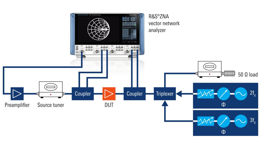
Harmonic load pull allows impedances to be controlled not only at the fundamental frequency but also at harmonic frequencies. The purpose is to optimize the transistor efficiency.
Benefits of our load pull testing solutions
The Rohde & Schwarz load pull measurement setup allows all parameter values of interest to be derived from the measured wave quantities. The user can also adjust the tuners to accurately measure and control the respective impedances presented to the DUT.
Our solution:
- Builds on a trusted VNA platform with the R&S®ZNA
- Provides the best support for harmonic load pull with its four internal sources for fundamental and harmonic drive - fully integrated and controlled in amplitude and phase
- Offers full system integration of hardware and software together with our partners
- Enables turnkey on-wafer integration for load pull
Do you want to explore the possibilities of load pull or need more details? Then feel free to contact us.


