Key facts
- Flexible distribution of digital port signals of the R&S®TS-PIO3B module
- Local +5 V/+12 V supply voltages
- Analog bus access
- Distribution of digital I/O ports
- Additional simple analog measurement channels


Key facts
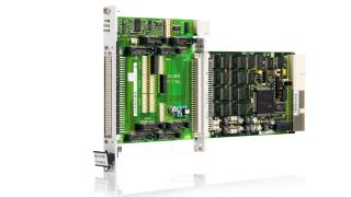
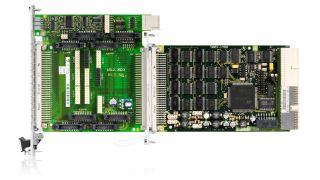
The R&S®TS-PTRF is an accessory module for routing digital control lines of the R&S®TS-PIO3B digital I/O module to the front panel of the R&S®CompactTSVP or R&S®PowerTSVP. In both instruments, the module is connected as a switching and distribution module in front of an R&S®TS-PIO3B or an R&S®TS-PTR signal transmission module and offers a variety of ways to route signals.
Manufacturer's recommended retail price (MSRP). The price shown does not include VAT. Prices and offers are only intended for entrepreneurs and not for private end consumers.
You may use the electronic signature via DocuSign to submit your information to enroll with the Rohde & Schwarz Customer Delegated Administration program. DocuSign processes the information provided according to their . The minimum system requirements for using the DocuSign system may change over time. The current system requirements are found
Terms & Conditions of the Prize Draw 10 years Rohde & Schwarz oscilloscopes
1. The prize draw “10 years Rohde & Schwarz oscilloscopes” (herein referred to as “Draw”) is organized by Rohde & Schwarz GmbH & Co. KG, Mühldorfstraße 15, 81671 Munich, Germany, Tel. +49 89 41 29 0 (herein referred to as “R&S).
2. All participators can register to the draw during January 01, 2020 to December 31, 2020 with their name, company name and business e-mail.
3. Participation is free of charge and not dependent on the purchase of goods or services.
4. The draw is only open to legal entities and only the legal entities are able to win the prizes. An individual person is not allowed to participate on its own name and its own account but as a representative of a legal entity filing the participation form in the name of and on behalf of the legal entity.
5. The prizes to win are 1 of 10 R&S®RTB2000 within the time frame January 1, 2020 to December 31, 2020:
Prize: 1x R&S®RTB2000 Digital Oscilloscope
6. The draw takes place at Rohde & Schwarz headquarters, Muehldorstrasse 15, 81671 Munich. The winner of the prizes will be informed by e-mail within 5 (5) working days.
7. The authorized representative of the legal entity shall inform Rohde & Schwarz about the acceptance of the price. In case of the denial of the acceptance, or no answer within two (2) weeks, a new winner will be drawn. If no winner can be determined within four (4) weeks, the draw ends and the prize forfeit.
8. R&S’ employees and members of their families and also person being familiar with the process of the draw and members of their families are excluded from filling the participation form.
9. No cash equivalent or exchange of prizes is allowed. Prizes are non-transferable. All taxes, levies, duties, fees and other charges levied in the participant´s country shall be borne by the participant.
10. Personal data will be processed only for the purpose of this prize draw and deleted four (4) weeks after the draw, if not agreed otherwise.
11. Any Participant who does not comply with these Terms & Conditions may be disqualified by R&S from this Competition. In such cases, prizes can also be withdrawn retrospectively. In case a prize is withdrawn retrospectively due to the non-compliance with these Terms & Conditions, it shall be returned by the respective participant at his cost to R&S’ address mentioned under Nr.1 and a new winner will be drawn.
12. The participants cannot claim the prizes of this draw and no legal recourse is permitted in this respect.
13. The draw and any contractual relationship arising therefrom between R&S and the respective participant shall be governed by and construed in accordance with the laws of Germany, without any recourse to the conflict of laws. The courts of Munich, Germany, shall have exclusive jurisdiction in case of any disputes arising directly or indirectly from the participation in this Competition.
* “fast delivery” inside 7 working days applies to the Rohde & Schwarz in-house procedures from order processing through to available ex-factory to ship.

