Reduce performance degradation of automotive radar sensors caused by radomes and bumpers
Your application
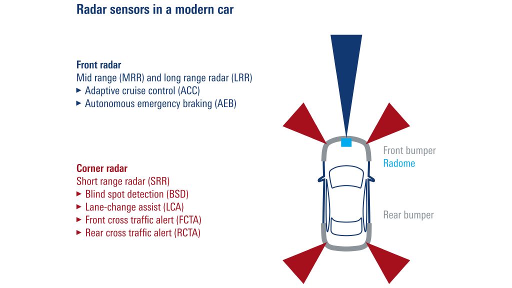
Vehicle radar systems emit frequency-modulated continuous wave (FMCW) chirps and then measure propagation delay and Doppler frequency shift of the reflected signal, which is then used to calculate the distances of other objects (such as other vehicles or passersby) and corresponding radial velocities. Current radar sensors measure the azimuth (angle in the horizontal plane) between the direction of travel and a detected object, as well as the elevation (angle in the vertical plane) between the vehicle and other objects.
Automotive radar sensors must be accurate and reliable, since vehicle control systems use their data to analyze the environment and decide whether or not to intervene in driving. A radar sensor misjudgment of one degree between two vehicles 100 m apart can result in a 1.7 m deviation and can have disastrous consequences.
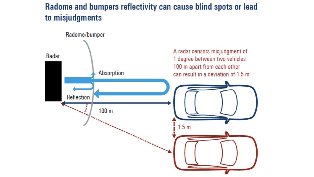
Radome and bumpers reflectivity can cause blind spots or lead to misjudgments
For aesthetic reasons, radar sensors are usually installed behind a vehicle emblem or bumper. This has functional disadvantages since radar signals have to pass through materials with an attenuating effect. Radomes and bumpers are part of the high-frequency sensor system and can have a massive negative impact on detection performance and accuracy.
Radomes and bumpers can attenuate the radar signal by several dB causing the overall autonomous driver assistance system (ADAS) to reach a shorter total range or cause squinting at the side radar. Radomes and bumpers can also cause a mismatch between the base material and the radar signal. The material properties of moulded plastic parts and semi-metallic surface coatings are often heterogeneous, generating unpredictable signal distortions in the received signal, such as phase distortions.
Millions of automotive radars are produced every year and car manufacturers are starting to deploy them as standard equipment in all high-end vehicles with mid-market and economy vehicles set to follow. Radar sensors are vital to autonomous driving, which makes them very relevant to vehicle safety. Demand is emerging to have every bumper and radome tested for their impact on the system during production to ensure overall safety for autonomous vehicles.
Your challenge
When developing and integrating radar sensors, the challenge is to ensure a certain level of performance despite various inherent systemic uncertainties. Any reduction in systemic uncertainty makes it easier to achieve the required performance. Radar sensor manufacturers can calibrate their products but RF system designers realize that sensor manufacturers cannot know the type of radome or bumper where their sensors will be installed or how the radomes and bumpers will be painted or any material irregularities they might have.
The radomes/bumpers need to be measured together with the sensor to make sure the entire system functions properly. Radome and bumper manufacturers are responsible for testing and validating the properties of their products in all phases, starting from the initial design phase all the way to the production line. Radome and bumper manufacturers need detailed, fast, robust and reliable tests in every phase – particularly in production.
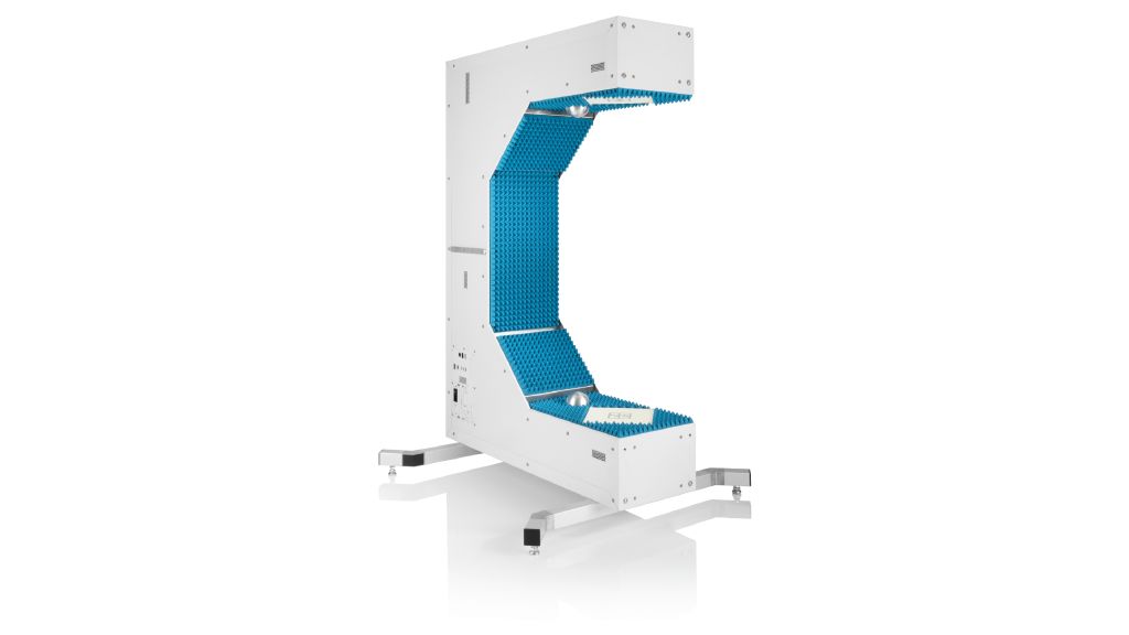
The R&S®QAR50 supports C-and U-shape assembly and can easily be integrated in test stands.
Rohde & Schwarz solution
Vehicle radar system performance is becoming ever more important, so Rohde&Schwarz developed the R&S®QAR50 quality automotive radome tester.
The R&S®QAR50 is ideal for accurately testing radome and bumper quality for the automotive radar frequency range in every product phase from R&D to end-of-line (EOL) testing. Hundreds of receive and transmit antennas quickly characterize materials, radomes and bumpers. The microwave imaging technology focuses on electronics and allows more flexible DUT positioning. The two clusters and customizable frequency bands enable the R&S®QAR50 to measure one-way transmission loss, reflection on both sides and transmission phase in a four second measurement cycle. The results can be directly compared with vector network analyzer free space measurements.
Measurement setup
Precise and repeatable reflection and transmission measurements depend on accurate positioning. Most test and measurement setups have limited space between their DUTs and the transmit and receive antennas. Bulky front and rear bumpers make it difficult to find sufficient space. The R&S®QAR50 has a large 990 mm (38.98 in) insertion space between the clusters for easy manual or automatic placement of a radome or bumper. The R&S®QAR can be integrated and operated upright in a C or a U position depending on the production line structure and requirements. This allows flexible positioning, simplifies handling and minimizes integration requirements.
Despite the large insertion space, the R&S®QAR50s is only 310 mm × 1420 mm × 970 mm (12.2 in × 55.9 in × 38.2 in) in size and can fit in most test stands. Rohde & Schwarz offers a ready-to-use solution with its partner, Löhnert Elektronik. The PC-based measuring and automation software from the system manufacturer, Löhnert Instant Scripting RunTime (LisRT V3), can control the test stand together with SPS from Siemens. In standalone mode, the R&S®QAR50 can be controlled with SCPI commands at no additional cost.

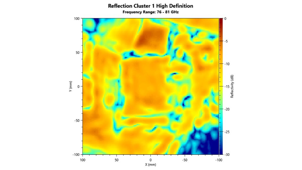
The R&S®QAR50-K30 shows a high-resolution image that allows quick detection of disturbances and makes the mounting structure of bumpers clearly visible.
Instrument setup
The two clusters in the R&S®QAR50 measure one-way transmission loss, reflection on both sides in the frequency range in one sweep between the bands 76 GHz to 77 GHz and 76 GHz to 81 GHz.
Before EOL radome and bumper testing, knowing the homogeneity of the parts is also important. The R&S®QAR50 can be equipped with an additional phase mask option for measurement on the transmission phase. This enables analysis of radome and bumper homogeneity without any mechanical movement.
The geometry and edges of radomes can also have significant influence on the radar signal. Microwave technology enables the R&S®QAR50 to display a high-resolution reflection image for quick anomaly detection. It also makes the mounting structure clearly visible for fast and correct DUT positioning.
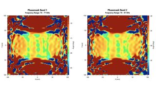
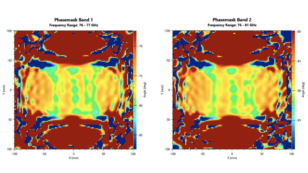
The R&S®QAR50-K20 measures the transmission phase and enables homogeneity analysis of the radome and bumper.
When radomes and bumpers are in production testing, the streamlined user interface provides all the necessary information at a glance. The simplified menu navigation means that even newcomers to RF technology can operate the unit. The instrument displays the numerical reflection values as well as transmission measurements and provides information about the DUT positioning. All this makes the values easy to understand and read. It also makes it ideal for end-of-line testing.
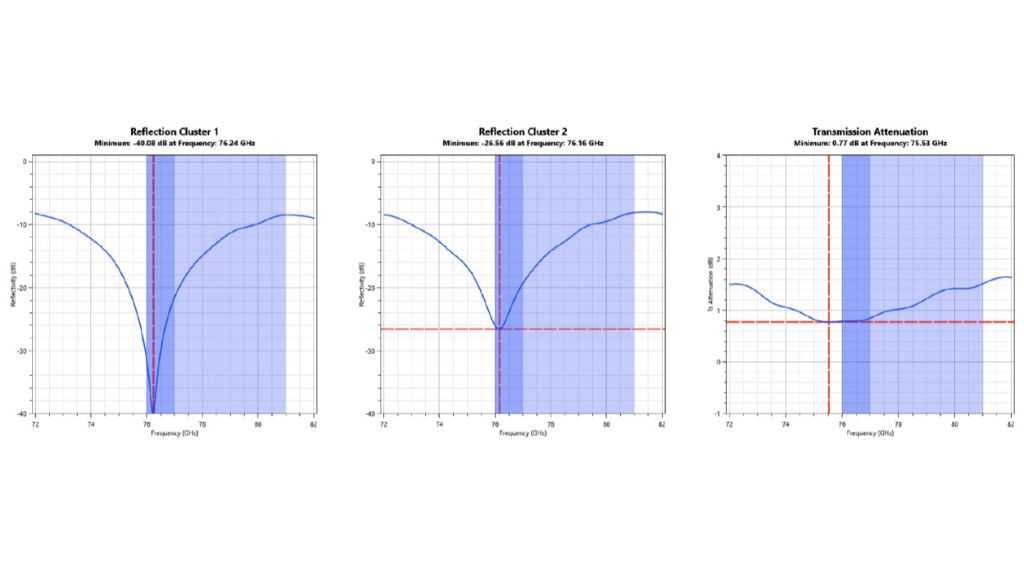
The R&S®QAR50-K10 extends the frequency range from 72 GHz to 82 GHz and shows the frequency response of transmission loss and reflection measurements.
Some OEM have higher requirements specifications in their EOL testing. The R&S®QAR50-K10 option can extend the frequency for both bands in the range from 72 GHz to 82 GHz, revealing the frequency response to reflection and transmission loss. This allows the correct frequency adaptation for the material to be detected and the material thickness to be adjusted as needed. In production, the reflection minimum allows quick detection of mismatches and fluctuations in the DUTs.
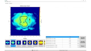
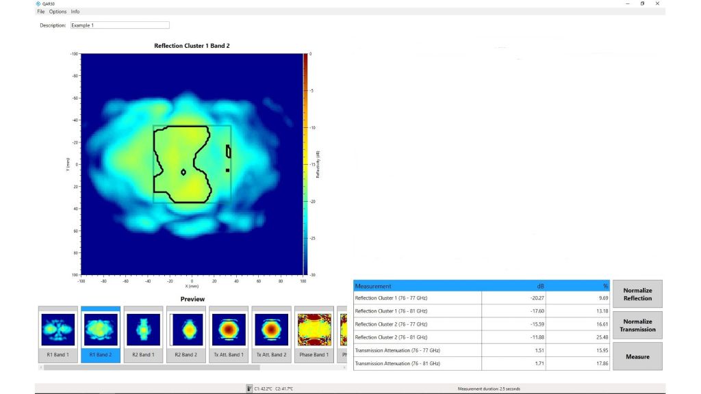
The R&S®QAR50 calculates numerical results, mean reflection for cluster 1 and 2 and frequency bands 1 and 2 as well as mean transmission attenuation for frequency bands 1 and 2 over a certain area of the DUT.
Measurement results
The powerful calculation hardware in the R&S®QAR50 can process large amounts of data in a short amount of time. The resulting images and frequency plots are available in seconds. Depending on the selected parameters and saved data, extremely fast cycle times of less than four seconds are possible. This makes the R&S®QAR50 ideal for high-throughput production lines.
Precision, reliability and robustness of measuring instruments are vital for equipment used in production testing. Reflections have a particularly large influence on radome and bumper quality and precision is essential. The R&S®QAR50 is the only EOL tester that directly measures reflection, and does not base calculations on transmission phase and loss information (which can be inaccurate). Time-gated measurements ensure optimized products and consistent quality in the manufacturing process.

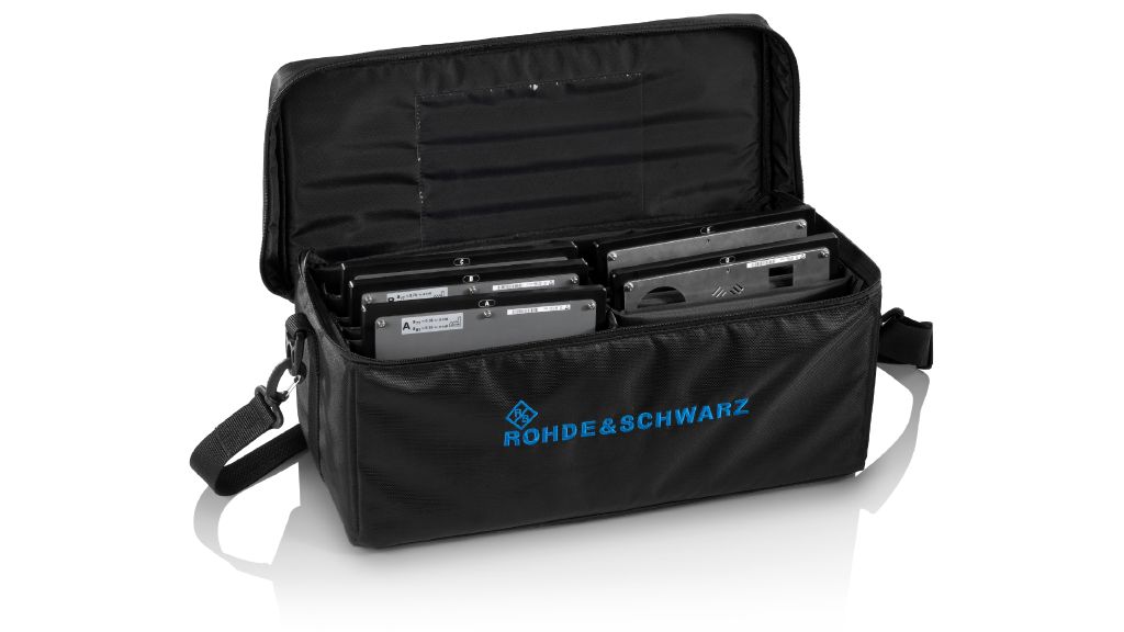
Compliant verification set to national and international standards.
To ensure the most accurate and repeatable measurement results, Rohde & Schwarz is the only vendor that performs accredited open space measurement/characterization. The R&S®QAR50-Z44 verification plates enable verification of transmission loss and reflection measurements in line with national and international standards.
Reports can quickly and easily be saved as .csv (includes all numerical values in .csv format), .json/.xml (includes all numerical values in .csv format), .png (all activated images), .mat (includes all image matrices or/and reconstructed volumes), to a USB device or in the network via SCPI.
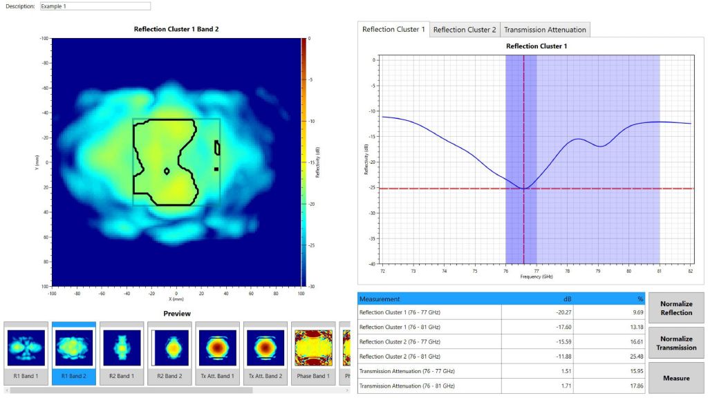
The R&S®QAR50 shows measured values for reflections, transmission loss, as well as phase masks and reflection image. The measurement results allow for easy comparison to VNAs, which are used as a reference in R&D.
Instrument maintenance
Correct instrument maintenance is essential and decisive in EOL testing, since this is the only way to ensure high throughput over a longer usage period. To minimize unforeseen maintenance, a major focus was on making sure moving parts were kept to a minimum inside the R&S®QAR50. This reduces wear and tear while minimizing downtime and maintenance costs.
T&M equipment needs to be regularly recalibrated for robust, reliable results and adequate performance within set limits. When calibrating standard T&M equipment, it usually has to be removed and set up for a special calibration procedure with calibration kits. This is time-consuming and requires special skills. The R&S®QAR50 uses built-in spherical reflectors to calibrate itself instantly while remaining in place. This makes calibration procedures fast and feasible, even for those without any RF skills..

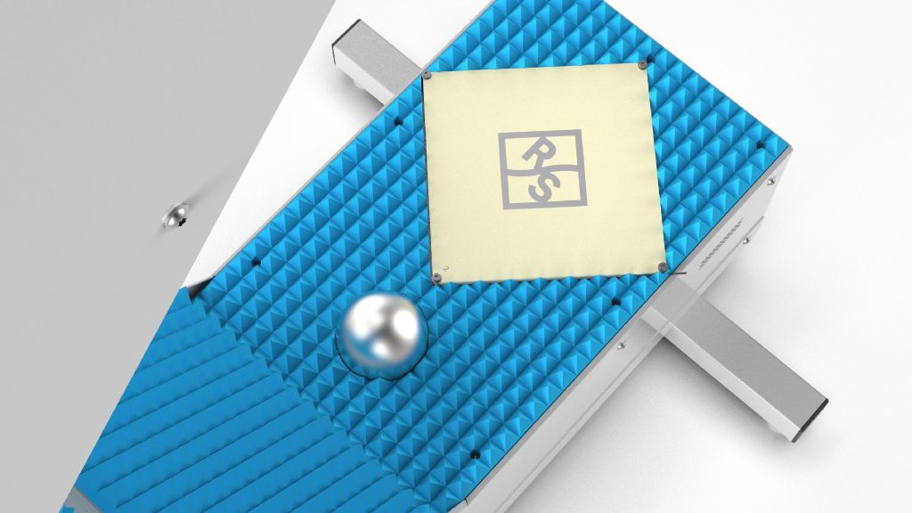
Due to the built-in spherical reflectors, the R&S®QAR50 can calibrate itself instantly while remaining in place.
Accuracy and reliability of safety-critical data
Autonomous driver assistance systems require access to reliable high-quality data from the various radar sensors to detect objects in their surroundings. Radomes and bumpers have a big impact on the quality and reliability of this data due to the inconsistent material properties in the RF signal path.
Testing and matching radome and bumper properties is too complex, costly and time-consuming after they have been installed in a vehicle. Manufacturers must test and validate the RF performance of every radome and bumper before they are installed in a vehicle.
The R&S®QAR50 is ideal for accurately testing radome and battery quality in the automotive radar frequency range in all production phases, especially in the EOL phase. It has enough space to easily accommodate bulky bumpers and make spatially resolved measurements to evaluate the homogeneity of design emblems. The innovative hardware concept enables very fast measurement times and the modular software concept can be tailored to specific requirements. The R&S®QAR50 delivers fast and precise radome and bumper testing at a very attractive price.


