Measurement setup
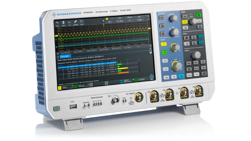
All that is needed to set up the soft-start measurement is a voltage probe at the switching element of the power supply. In a simple buck converter design, the gate of the switching element is the preferred choice.
Device setup
After connecting the probe to the circuit under test, the measurement can be started according the following instructions:
- Set the trigger mode to normal mode and activate single trigger acquisition
- Set the acquisition time to a sufficient value
- Set the horizontal scale to a sufficient value
- Set the trigger level to a sufficient level
- In the Math menu, activate “track pulse width” with the use of the PWM control signal
- Configure channel 2 to measure the output voltage. This is only a reference signal
- Start the power supply by switching on the input voltage
Measurement result
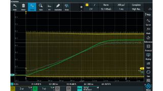
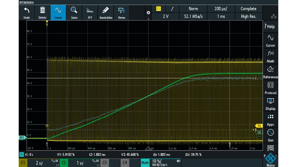
Channel 1 displays the connected PWM control signal. The Math channel shows the duty cycle of the control signal. Channel 2 displays the output voltage of the converter and is only measured to compare the output voltage with the math signal.
It is remarkable that the rise time of the output voltage curve is very close to the timing of the tracking graph.
However, the great advantage of this tracking measurement is that for each switch on/off cycle, the duty cycle is visible in the track curve. The soft-start algorithm in the controller limits the rise time of the duty cycle graph. The output current follows the duty cycle graph. But unlike with the direct output voltage measurement, the user is able to easily observe any single erroneously generated duty cycle. In the output voltage graph, it may be difficult to observe any spikes in the slope because the output filter may suppress short events.


