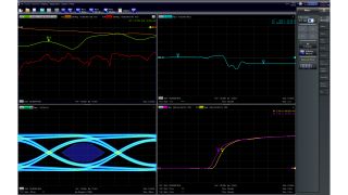
Key facts
- Rise time resolution from 9 ps
- Formats: lowpass impulse and step, bandpass impulse
- Windowing/time gates: rectangular, hamming, Hann, Bohman, Dolph-Chebychev
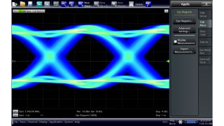
- Signal integrity test function with eye diagram


Key facts
The time domain and distance-to-fault options display discontinuities, reflection factors or impedance versus delay/length. The TD option includes step and impulse response, lowpass/bandpass, frequency spacing and gated S-parameters. A wide selection of windows can be used to optimize the time domain response and suppress sidelobes due to the finite sweep range. Time gating and transforming back to the frequency domain eliminates unwanted responses.
The right format for the right application
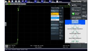
The Rohde & Schwarz time domain option supports the following formats: lowpass impulse and step, bandpass impulse. The easy-to-use bandpass mode works with any set of a harmonic grid. The lowpass mode offers higher resolution factors in the DC value information.

Optimize measurement results with windowing and gating
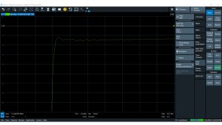
The finite sweep range in frequency domain measurements with discontinuous transitions at the start and stop frequency broadens the impulses and causes sidelobes (ringing) in the time domain response. Windowing can reduce this effect and optimize the time domain response. A time gate is used to eliminate unwanted responses that appear on the time domain transform. An active time gate acts on the trace in time domain and frequency domain representations.

Valuable insights into the signal integrity of your design
The enhanced time domain option enables the R&S®VNA to implement a "virtual" signal generator for generating multilevel PAM signals (NRZ, PAM-4, PAM-8, PAM-16), including simulated lowpass behavior. The eye diagram calculated from the DUT's measured S-parameters provides an extensive overview of the system's signal integrity. Further building blocks for pre-emphasis, jitter, noise and equalization enable synthesization of the transmission system's transmitter and receiver parts.

Optimum resolution for optimum results
The Rohde & Schwarz time domain options offer a minimum resolution of up to 18 ps with an ambiguity range of up to 1.5 µs depending on the instrument of choice. Rise time resolution is as narrow as 9 ps. For more information, see the comparison table.
Order number 1332.5336.02
Order number 1164.1657.02
Order number 1316.0156.02
Order number 1318.8425.02
Order number 1328.5393.02
Order number 1306.0201.02
Order number 1323.1819.02
Order number 1351.5367.02
Order number 1326.8072.02
Extended time domain analysis
Order number 1319.4400.02
Extended time domain analysis with eye diagram
Order number 1351.5373.02
Extended time domain analysis
Manufacturer's recommended retail price (MSRP). The price shown does not include VAT. Prices and offers are only intended for entrepreneurs and not for private end consumers.
You may use the electronic signature via DocuSign to submit your information to enroll with the Rohde & Schwarz Customer Delegated Administration program. DocuSign processes the information provided according to their . The minimum system requirements for using the DocuSign system may change over time. The current system requirements are found
Terms & Conditions of the Prize Draw 10 years Rohde & Schwarz oscilloscopes
1. The prize draw “10 years Rohde & Schwarz oscilloscopes” (herein referred to as “Draw”) is organized by Rohde & Schwarz GmbH & Co. KG, Mühldorfstraße 15, 81671 Munich, Germany, Tel. +49 89 41 29 0 (herein referred to as “R&S).
2. All participators can register to the draw during January 01, 2020 to December 31, 2020 with their name, company name and business e-mail.
3. Participation is free of charge and not dependent on the purchase of goods or services.
4. The draw is only open to legal entities and only the legal entities are able to win the prizes. An individual person is not allowed to participate on its own name and its own account but as a representative of a legal entity filing the participation form in the name of and on behalf of the legal entity.
5. The prizes to win are 1 of 10 R&S®RTB2000 within the time frame January 1, 2020 to December 31, 2020:
Prize: 1x R&S®RTB2000 Digital Oscilloscope
6. The draw takes place at Rohde & Schwarz headquarters, Muehldorstrasse 15, 81671 Munich. The winner of the prizes will be informed by e-mail within 5 (5) working days.
7. The authorized representative of the legal entity shall inform Rohde & Schwarz about the acceptance of the price. In case of the denial of the acceptance, or no answer within two (2) weeks, a new winner will be drawn. If no winner can be determined within four (4) weeks, the draw ends and the prize forfeit.
8. R&S’ employees and members of their families and also person being familiar with the process of the draw and members of their families are excluded from filling the participation form.
9. No cash equivalent or exchange of prizes is allowed. Prizes are non-transferable. All taxes, levies, duties, fees and other charges levied in the participant´s country shall be borne by the participant.
10. Personal data will be processed only for the purpose of this prize draw and deleted four (4) weeks after the draw, if not agreed otherwise.
11. Any Participant who does not comply with these Terms & Conditions may be disqualified by R&S from this Competition. In such cases, prizes can also be withdrawn retrospectively. In case a prize is withdrawn retrospectively due to the non-compliance with these Terms & Conditions, it shall be returned by the respective participant at his cost to R&S’ address mentioned under Nr.1 and a new winner will be drawn.
12. The participants cannot claim the prizes of this draw and no legal recourse is permitted in this respect.
13. The draw and any contractual relationship arising therefrom between R&S and the respective participant shall be governed by and construed in accordance with the laws of Germany, without any recourse to the conflict of laws. The courts of Munich, Germany, shall have exclusive jurisdiction in case of any disputes arising directly or indirectly from the participation in this Competition.
* “fast delivery” inside 7 working days applies to the Rohde & Schwarz in-house procedures from order processing through to available ex-factory to ship.


