Interested?

R&S®Essentials | Digital oscilloscope and probe fundamentals

Oscilloscope buyer's guide

Guide to choosing an oscilloscope

Oscilloscopes are easy-to-use instruments with a wide range of specifications, options, and capabilities. They display waveforms that let you characterize signals and debug circuit issues. Their flexibility has the benefit that they can make many measurement types across multiple domains. With so much capability, it is essential to understand what specifications mean when choosing an oscilloscope.

What is an oscilloscope?

An oscilloscope is an instrument that displays waveforms as voltage across time. These "real-time" instruments capture signals as they change. Typically, they have a screen to display waveforms and measurements, controls to change settings like volts per division, and input connectors for cables or probes.

Bandwidth

What does bandwidth mean?

Bandwidth is the range of frequency content an oscilloscope can measure. Oscilloscopes are one of the few wideband instruments that measure from DC (0 Hz) to their specified bandwidth. This specification is the most important when buying an oscilloscope because you cannot make accurate measurements if an oscilloscope does not have enough bandwidth.

Definition of oscilloscope's bandwidth

The frequency response of an oscilloscope's front-end amplifier resembles a low-pass filter. That shape means it passes most signal content from DC to where the attenuation drops by 3 decibels (dB). The -3 dB point is where oscilloscopes define their "bandwidth" and represent approximately a 30% reduction in voltage at that frequency point.

How to choose what bandwidth you need?

Picking a bandwidth for a specific application can be complicated when choosing an oscilloscope. For example, if you only plan to look at sine waves, you only need to ensure you have slightly more bandwidth than the maximum carrier frequency to account for the 3 dB attenuation. So, for example, if you need to measure a 100 MHz sine wave, you might select an oscilloscope with 150 MHz or more bandwidth.

Estimated bandwidth based on sine waves

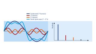
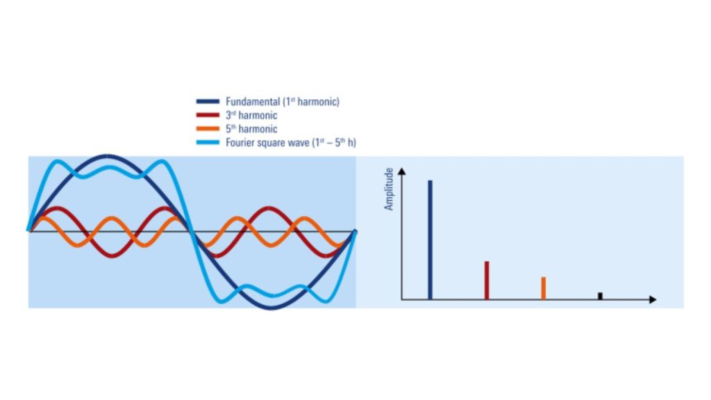
If, however, your waveform is more complex, like a digital signal, then there are multiple considerations. One guideline for digital or other complex signals is to pick a bandwidth that is 3-5 times faster than the fastest clock or data signal. For example, if measuring a memory bus with a data rate of 133 MHz, you would pick a bandwidth of at least 400 MHz. However, this guideline assumes that a digital signal's rise time is related to the data rate.

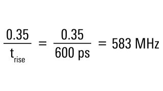
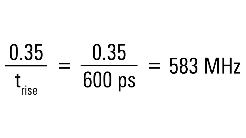
Bandwidth estimation with 0.35 over-the-rise time equation

The rise and falling edges in digital signals tend to have more frequency content than the fundamental frequency. Therefore, using the equation 0.35 over the rise time provides a first-order estimation of the bandwidth in the signal. For example, consider the previous bus example. If we say the signal has a 600 picosecond rise time, using the equation above, we can see there is frequency content up to 583 megahertz! (That value falls within the 3-5 times the data rate guideline.)

Other bandwidth considerations

Most oscilloscopes have upgradeable bandwidth options. Of course, there is a maximum to what they can upgrade to, but there could be a path forward if you find the bandwidth is too limiting.

Too much bandwidth can affect your measurement. In general, more bandwidth in a measurement also means more broadband noise. Fortunately, many oscilloscopes offer filters to reduce the front end's bandwidth. For example, all Rohde & Schwarz oscilloscopes have a 20 MHz filter for power supply measurements. In addition, models like the R&S®MXO 4 and R&S®RTO 6 have an "HD mode" to trade off bandwidth and ADC resolution for high accuracy on low-bandwidth measurements.

You have questions? Contact us.

Sample Rate

What does sample rate mean?

The analog-to-digital converter (ADC) in an oscilloscope digitizes the analog signal. The rate it digitizes is called the "sample rate." Manufacturers specify the sample rate as samples per second. For example, the 300 MHz R&S®RTC1000 oscilloscope has a 2 gigasample per second sample rate. You might also see the sample rate written as 2 Gsample/s, 2 GaSa/s, or even 2 GSp/s.

How to choose what sample rate you need?

At a minimum, an oscilloscope's sample rate should be least 2.5 times higher than the bandwidth. For example, if the oscilloscope has 1.5 GHz of bandwidth, the sample rate should be higher than 3.75 gigasamples per second. In general, most digital oscilloscopes meet this minimum requirement. However, an oscilloscope might interleave multiple channels to achieve the fastest sample rate.

For example, the 300 MHz R&S®RTC1000 samples at 2 Gsample/s on a single channel but only 1 Gsample/s when both channels are enabled. Fortunately, even at this reduced sample rate, the R&S®RTC1000 still over samples greater than 2.5 times the analog bandwidth!

In general, a higher sample rate is better.

Other sample rate considerations

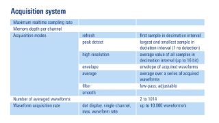
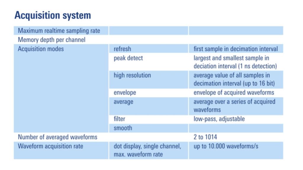
Oscilloscopes have different acquisition modes, such as "peak detect" or "high-resolution." These modes allow the ADC to continue running at its maximum sampling rate but reduce the amount of data points stored in memory. These modes make higher sample rates useful for applications with relatively slow signals.

ADC Bits

What are ADC Bits?

An oscilloscope's analog-to-digital converter outputs binary values. Like any ADC, the number of bits making up the binary values determines the resolution. For example, an 8-bit ADC outputs 256 unique values or voltage levels. While a 10-bit ADC outputs 1,024 unique values and a 12-bit ADC outputs 4,096 voltage levels.

Accuracy versus Resolution (versus Sensitivity)

While an ADC's resolution affects an oscilloscope's measurement accuracy, it is not the only aspect to consider.

The definition of accuracy is the difference between the expected measurement and the actual value. In other words, it is the uncertainty of a measurement. The resolution, on the other hand, is the smallest change that a measurement system can represent. In the case of an oscilloscope, the ADC's bit width dominates the resolution. Last, sensitivity is the smallest detectable change. At first, this definition may sound the same as resolution, and individual elements of an acquisition system may have very high sensitivity. However, the overall sensitivity is the combination of accuracy and resolution.

Other Considerations

Not all oscilloscopes operate at full bit width all of the time! Therefore, you should carefully review the datasheet to understand any limitations. Fortunately, all R&S oscilloscopes use their full bit width at all times.

Additional, some R&S oscilloscope models can increase their effective bit width with feature called HD Mode. This mode trade-offs bandwidth for higher resolution measurements. For example, the R&S®MXO4 offers a 12-bit ADC which can effectively increase up to 18 bits!

Triggering

What does Trigger mean?

In digital oscilloscopes, the trigger system watches the signal(s) under test for specific events. When it detects these user-selectable criteria, it creates a trigger action. The most common trigger type is the edge-level trigger, and the most common action is to update the screen with the event at the center.

Trigger systems can identify many other events, such as pulse widths, runt voltages, logic levels, and serial protocol packets. They also have several tools to filter out noise, qualify valid events, and trigger other instruments.

How do you choose which trigger features you need?

A full-featured trigger system can significantly reduce debug time and make it possible to characterize very complex signals.

The first consideration is what types of triggers an oscilloscope supports. Then, you can look at its other capabilities, such as adjustable hysteresis and sequence triggering.

An adjustable hysteresis means the trigger can tolerate more noise on a waveform or focus on a specific event on an edge. For example, oscilloscopes with precise digital trigger systems can trigger on events smaller than 0.0001 of a vertical division!

Sequence triggering, sometimes called A->B triggering, allows you to create a two-stage trigger condition. For example, you can qualify a particular pulse width only after the falling edge of an enable signal.

Other Triggering Considerations

When evaluating an oscilloscope's trigger system, paying careful attention to its specifications is essential. Some oscilloscope trigger systems may only be "full bandwidth" on the edge trigger. The other trigger types may be relatively slow compared to the oscilloscope's bandwidth.

Oscilloscopes like the R&S®MXO4 and R&S®RTO6 utilize a digital trigger system. Instead of relying on an analog circuit to identify events, a custom ASIC watches the digital samples from the ADC in real-time to detect trigger events. This unique trigger method provides the most precise triggering capability. A significant advantage to such a system is that all trigger types are full-bandwidth. For example, a digital trigger's glitch detection is as fast as a single sample period of the ADC! Another benefit is the incredible voltage sensitivity.

Memory Depth

What does memory depth mean?

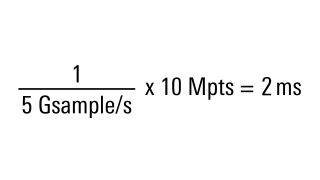
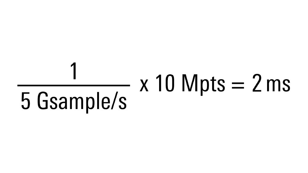
The ADC stores its samples in a memory buffer. Because ADCs tend to sample in the gigabit range, this memory must be close to the ADC and very fast. The amount of stored acquisition samples is called the "memory depth." For example, if a channel has a 10 megapoint buffer, it keeps (up to) ten million samples during each acquisition.

Memory depth calculation

There is a direct connection between how fast an oscilloscope samples, how much memory it has, and how much time it can capture. The timebase setting determines the minimum time an oscilloscope captures a signal. The acquisition system will balance memory depth and sample rate to maximize the sample rate for a given timebase setting. The more memory available, the slower (longer) the timebase setting can be while maintaining a high sample rate.

In general, more memory is better. However, some oscilloscopes do not maximize the use of their deep memory or become extremely slow when operating with deeper memory enabled.

How to choose what memory depth you need?

Unlike the other key oscilloscope specifications, there are no simple guidelines for memory depth. However, if you know you need to capture a certain amount of time, you can determine the minimum memory depth you need. For example, to capture 10 cycles of a 100 MHz clock signal, you would need to capture at least 100 nanoseconds. At 1 Gsample/s, the ADC samples every nanosecond. So you would need a memory depth of 100 samples.

Other memory depth considerations

A consideration for shallow versus deep memory is how the oscilloscope processes its acquisition memory. For example, R&S®MXO, R&S®RTO, and R&S®RTP oscilloscopes have custom ASICs to help manage deep memory operations. This ASIC keeps the oscilloscope responsive while zooming in/out of waveforms and minimizes the trigger re-arm time during acquisition.

Fast Segmentation and History Mode

Other considerations are modes or features that use memory other than simple acquisitions. For example, the Fast-Segmentation feature and History mode on R&S oscilloscopes use deep memory in valuable ways.

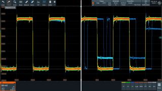
Acquisition of signal segments with activity

With fast segmentation, the acquisition system divides the memory into small (but equal) chunks--or segments. Then these chunks are filled as fast as the trigger system can re-arm itself. The memory controller waits until it fills all segments before transferring the acquisition data to the CPU. A fast segmentation mode has the benefit of re-arming the trigger system as fast as possible and maximizing the use of deep memory. It is beneficial for signals that have a bursting nature.

Display and analysis of each signal element

History mode is another novel way to use deep memory. The memory controller divides the total available memory into chunks or segments, like the fast segmentation mode. However, the controller fills the segments as a ring buffer with the oscilloscope processing each segment like in normal operation. The difference with history mode is that when you stop the oscilloscope, you can "dial back" in time to previous acquisitions. This feature is advantageous because it gives you time to hit the "stop" button after seeing an anomaly on the screen.

You have questions? Contact us.

Waveform Update Rate

What does waveform update rate mean?

The waveform update rate is sometimes called the trigger rate. It is how fast the oscilloscope can acquire waveforms between trigger event. In general, the quicker an oscilloscope re-arms and re-triggers, there is the less dead time between acquisitions.

Dead time is the time between acquisitions when the oscilloscope cannot capture a waveform. The lower the dead time, the faster the trigger rate, and the more likely an oscilloscope can capture infrequent events like a transient pulse.

Waveform acquisition between trigger events

Some Rohde and Schwarz oscilloscopes have a custom ASIC that enables ultra-fast waveform update rates. For example, the R&S®RTO6 can acquire up to 1 million waveforms per second. And the R&S®MXO 4 can acquire over 4.5 million waveforms per second!

Other waveform update rate considerations

Different measurements, acquisition modes, and memory depths can affect the waveform update rate. Some oscilloscope manufacturers may specify their maximum update rate (or minimum dead time) only when special modes are enabled. Therefore, when looking at this specification, it is essential to understand under what conditions the fastest rate applies.

Probes

What are oscilloscope probes?

Before you can measure a signal, you must get it into an oscilloscope. Sometimes, you can use BNC (or SMA) cables to connect directly from a device-under-test into the oscilloscope's front panel. However, in most cases, you need to use a probe.

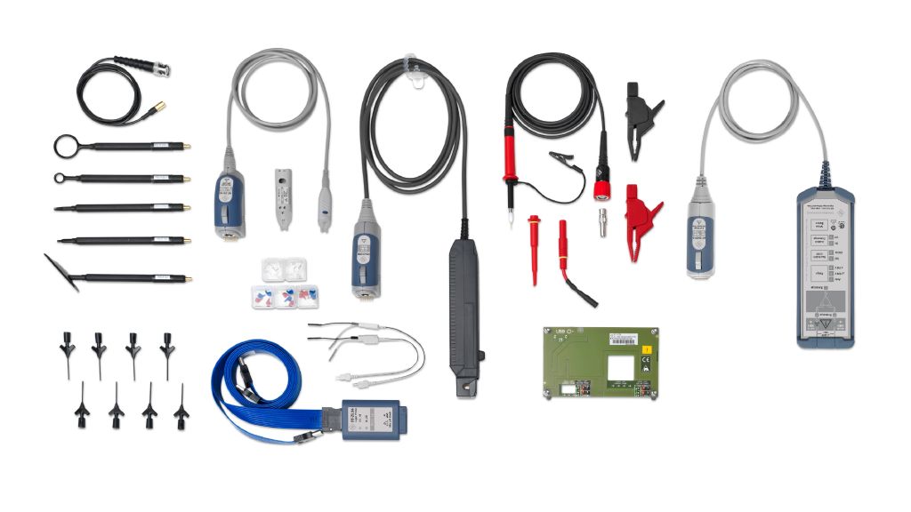
Rohde & Schwarz oscilloscope probe portfolio

How to choose which probes you need?

The most common probe type is the passive voltage probe. These inexpensive probes are suitable for general purpose applications. Probes with different attenuation factors offer either higher-voltage or low-loading of a signal.

Passive probes that come with an oscilloscope are generally rated at or slightly higher than the oscilloscope's bandwidth. Most passive probes do not exceed 500 or 700 MHz of bandwidth. An active voltage probe is necessary for probing signals with more than 700 MHz of bandwidth.

Active voltage probes use an amplifier circuit that offers higher bandwidth and lower circuit loading than passive probes. They come in single-ended, differential, and modular form factors. As their name implies, these probes require power for operation.

Some probes measure quantities other than voltage. For example, hall-effect sensor current probes non-intrusively measure the current through a wire. Another example is near-field probes that measure electromagnetic fields emitted from components, wires, and PCBs.

In general, active probes for one oscilloscope manufacturer may not be compatible with another. However, some manufacturers do offer adapters for other vendors' probes. (If planning to use one of these adapters, verify the probe is compatible with the adapter!)

Rohde and Schwarz has a wide variety of passive, active, and non-voltage probes with multiple form factors.

Other oscilloscope probe considerations

Oscilloscopes with lower bandwidths, generally less than 200 MHz, only support a passive probe interface. In other words, they only have a BNC connector on the front. On the other hand, an oscilloscope with more than 200 MHz may have an active probe interface that supports both passive and active probes.

Integrated Instruments

Oscilloscopes have grown beyond just a measurement tool for waveforms. When choosing an oscilloscope, consider the other instruments integrated into them. Here are some additional capabilities to consider.

Spectrum Analysis (FFT) with Oscilloscopes

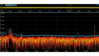
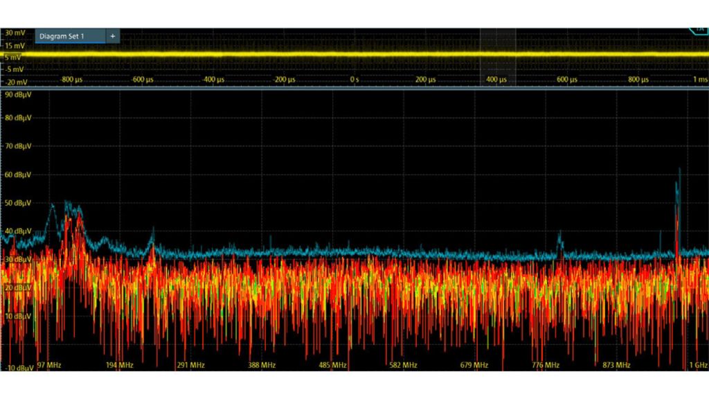
A Fast Fourier Transform, or FFT, converts time domain waveforms into a frequency domain plot. The oscilloscope display shows frequency and magnitude (instead of time and amplitude). Unlike traditional spectrum analyzers, oscilloscopes with spectrum analysis capability can measure down to 0 Hz or DC!

FFT function on an oscilloscope

FFTs may either be implemented as a simple math function with limited controls or hardware-accelerated with spectrum analyzer-like controls. In addition, the R&S RTO6 offers a unique Zone Trigger capability that allows you to drop a box where a spur might (or should not) occur to limit screen updates to a frequency of interest.

Arbitrary Waveform Generator

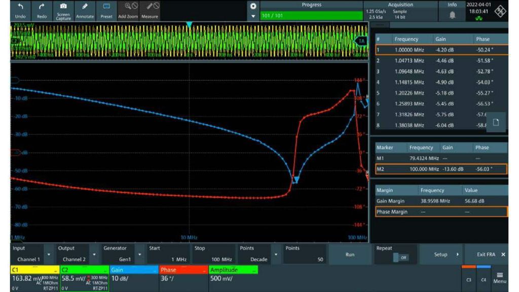
A built-in arbitrary waveform generator outputs functions like sine, triangle, and square waves with modulations like AM, FM, FSK, and PWM. Having a generator built into the oscilloscope can save space on your bench. In addition, many oscilloscopes can use the generator to create a signal to go into a circuit, while an analog channel measures the output. For example, the R&S®MXO4-K36 frequency response analysis (FRA) option creates bode plots of a power supply's control loop response (CLR) and power supply rejection ratio (PSRR).

Example of an arbitrary waveform generator example

Most Rohde and Schwarz oscilloscopes offer an arbitrary waveform generator option as either a software option or a plugin hardware module.

Logic Analyzer

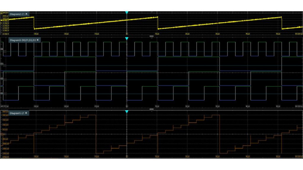
Oscilloscopes with digital channels can capture both analog and digital waveforms. Logic channels are typically time-correlated, meaning the oscilloscope samples them simultaneously with the analog channels. This capability results in the display showing events on both channel types locked-in time.

Mixed signal analysis for oscilloscope

All Rohde and Schwarz oscilloscopes offer digital channels as an option. Depending on the model, either 8 or 16 channels are available.

Protocol Analyzer

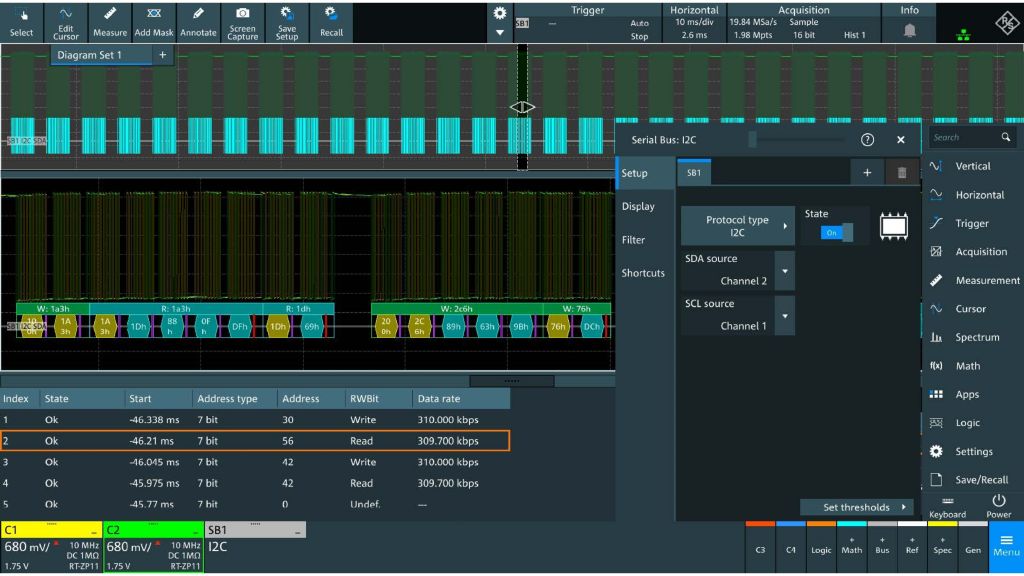
Protocol analysis takes the acquired waveform (on either the analog or digital channels) and decodes the it into a protocol display. For example, many microcontroller-based designs feature an SPI, I2C, or UART bus for communication. Using an oscilloscope's protocol analyzer features, you can trigger protocol-specific events, like the start of a packet or, in some cases, a CRC error. Once triggered, a decode display makes it easy to read bus transactions.

 Two ways of viewing protocol data
Two ways of viewing protocol data

There are at least two ways to view the data. One is to see an overlay on top of the acquired waveform. This view is beneficial in determining if a signal integrity issue is causing a protocol problem. Another view is a protocol table. This compact view lets you see a lot of protocol activity in a short period.

All Rohde and Schwarz oscilloscopes offer various decode options that can be included at the time of purchase or enabled after purchase.

Form Factor (Style)

Oscilloscopes come in a variety of sizes. In general, the higher the bandwidth, the larger the box. Portable oscilloscopes now have as much capability as the traditional bench style.

Bench Oscilloscopes

Typically, when someone pictures an oscilloscope, the bench form factor comes to mind. There is a front panel with a large screen, some knobs, a few buttons, and an array of BNC connectors. Most bench oscilloscopes also have a rack-mount option.

Portable Oscilloscopes

Two aspects identify a portable or handheld oscilloscope like the R&S RTH: its form factor and battery. This oscilloscope features a touch-screen. Instead of function specific-knobs, it has large push buttons and multipurpose rotary control, which you can easily actuate while wearing bulky gloves or when you are not directly in front of the instrument. The R&S RTH has bandwidth options up to 500 MHz, sample rate is up to 5 Gsample/s, and a 10-bit ADC. In addition, it has a full-featured digital trigger system and a wide range of automated measurements. Last, this oscilloscope has isolated inputs and comes with 4 analog channels or 2 analog channels and a hardware DMM.

You have any product questions? Contact us.

Remote Control

What does remote control mean?

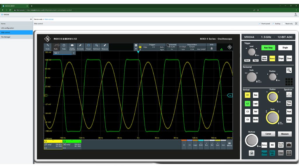
Remote control means connecting to the instrument from a PC and controlling it as if you were sitting in front of it. In this use model, you click buttons or knobs on a virtual front panel via a web browser that mimic the instrument's front panel.

 MXO remote access via web browser
MXO remote access via web browser

How to choose what kind of remote access you need?

If you need to access the oscilloscope remotely from your lab, make sure it supports the remote operation. For example, R&S®RTB, R&S®RTM, R&S®MXO 4, R&S®RTO 6, and R&S®RTP all support a virtual front panel through a web-based browser interface.

Other remote access considerations

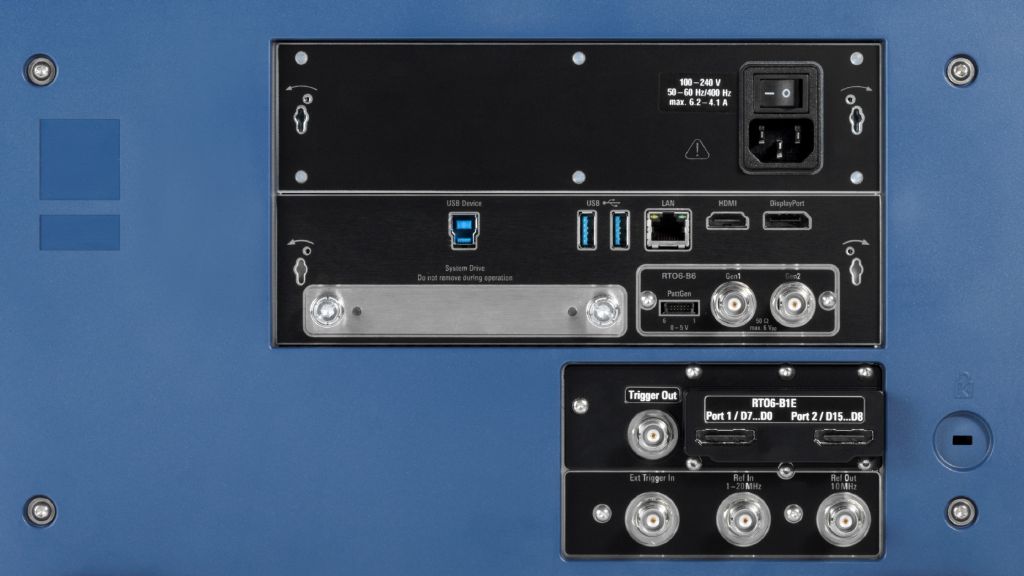
Most oscilloscopes that support GPIB require an additional hardware option to be purchased.

Oscilloscope rear panel with optional GPIB slot

Automation (and connectivity)

What does automation (and connectivity) mean?

Automation means controlling an instrument from a PC through a programming environment like NI's LabView™, MathWorks's MATLAB®, or Python. These environments send commands to the oscilloscope over USB, Ethernet, or GPIB.

Summary

  • Choosing the right oscilloscope is an important decision. The most important specification to consider is the bandwidth. After that you can consider other aspects.
  • Fast waveform update rates significantly reduce debug and characterization tasks. Generally, if the waveform update is accelerated, then the oscilloscope can handle deep memory very fast as well.
  • When looking at triggering capabilities, consider more than just what modes are available. Check that the specifications on each of those modes match your application's needs and evaluate critical factors like voltage sensitivity.
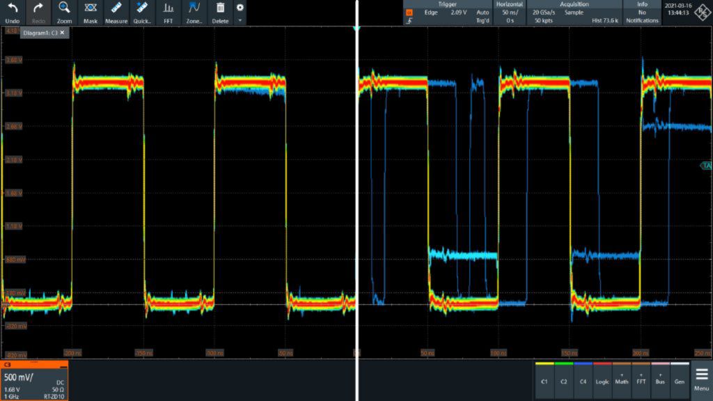
  • Remember, oscilloscopes now incorporate multiple test instruments. For example, if the oscilloscope has a fast and responsive FFT, it can act as a real-time spectrum analyzer. Or, with protocol triggers you can use it as a logic analyzer.
  • Last, there are a variety of form factors from handheld to portable to bench to suit a wide range of use cases.

If you have questions

Curious to learn more about test fundamentals?

Sign up for our newsletter