Measuring inrush current

All electronic devices have capacitive or inductive parts that that generate inrush current when switched on. This is more than just a part of operations – it is a vital aspect and demands keen oversight. The R&S®NPA power analyzers are the right instrument for the job.

Your task

From FPGAs to drilling machines, virtually every component or device has an inrush current far exceeding the normal operating current. Inrush current is particularly important for switching mode power supplies. The inrush current needs to be correctly determined to properly design circuitry or calculate safety‑relevant factors.

Rohde & Schwarz solution

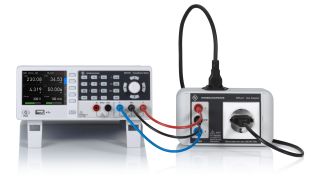
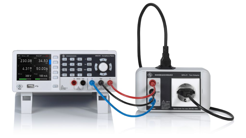
The R&S®NPA501 power analyzer and R&S®NPA701 compliance tester seamlessly acquire and process signals in real time with a high dynamic range. The versatile display provides fast and reliable results.

The internal current measurement range is ±15 mA to ±60 A (peak). An additional sensor can extend the current measurement range. The input can be combined with external current sense resistors to display smaller current ranges or combined with current probes to display larger ones. R&S®HZC51 current probe extends the current measurement range to ±1000 A.

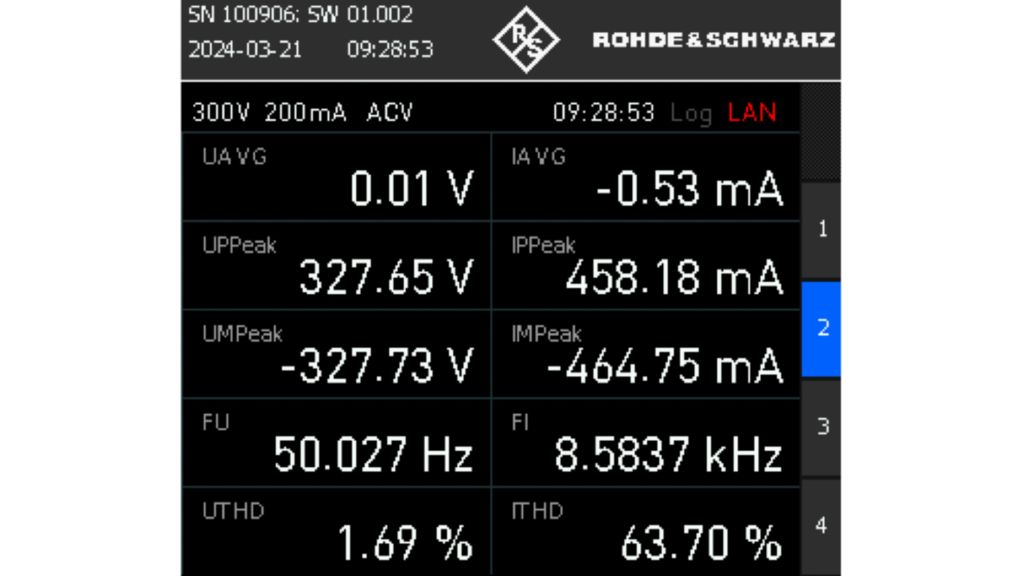
Numerical view of the measured values
Open Lightbox

Numerical view

If just the maximum inrush current needs to be measured (e.g. to determine cable thickness) a numerical display can be used to view direct results. The peak value is IPPeak. If outliers need to be captured, the DUT must be switched off and on several times. The maximum peak value is then determined with the Peak Hold function.

The current range should be manually set to meet the expected current with the Range Up button. Autorange mode can be reactivated by holding down the Range Up button

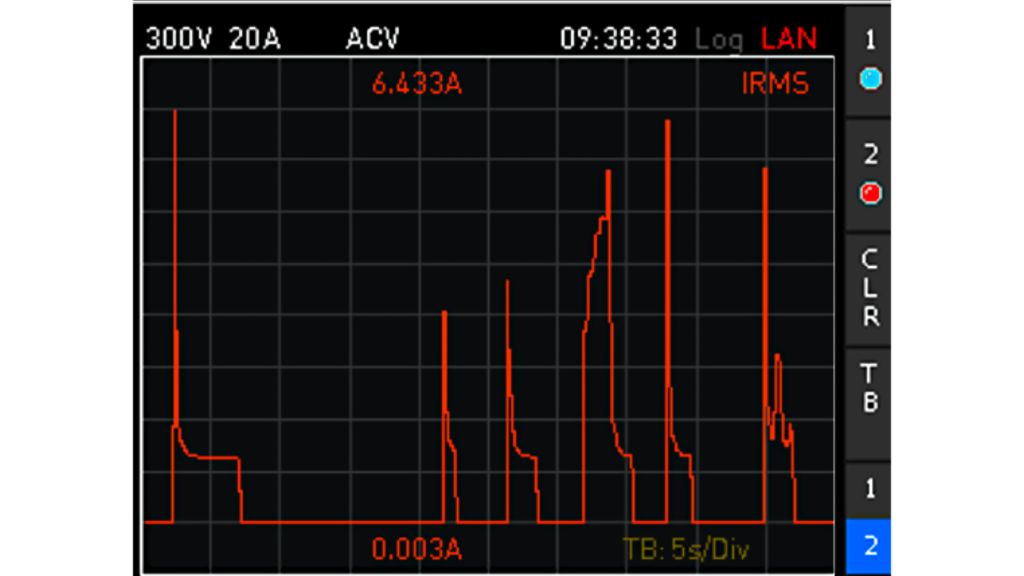
Trend chart view showing six example switch-on operations for the DUT
Open Lightbox

Trend chart view

The trend chart view shows the differences between individual switch‑on operations. The characteristics of multiple switch‑on operations can be easily recorded and compared.

The Hold button pauses measurements. Holding down the SAVE/RECALL button will save a screenshot to a USB flash drive.

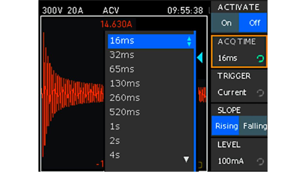
Inrush view for a drilling machine during power-up
Open Lightbox

Inrush view

The Inrush view provides more precise analysis of switch‑on operations (e.g. to determine the melting integral of a fuse). Non‑compressed acquisition of up to 8192 voltage and current points is possible with a logging period from 16 ms to 67 s. A number of trigger options are also available. The ACQ TIME button can be used to adjust the recording time as needed.

Measurement documentation

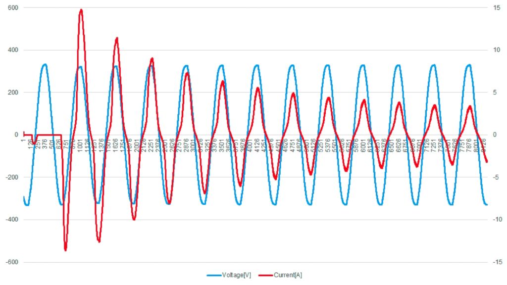
After a successful measurement, the precise data can be conveniently saved to a USB flash drive as a configurable CSV file. The data can then be evaluated on a PC using standard data processing software.

Summary

The R&S®NPA501 power analyzer and R&S®NPA701 compliance tester from Rohde & Schwarz efficiently measure inrush current in devices to help with circuit design and safety component calculations. They provide real-time analysis, extendable current measurement ranges and customizable data views for precise results.

Data evaluation, e.g. in Excel or MATLAB®