Analyzing RF radar pulses with an oscilloscope

Analyzing RF pulses is a key aspect of pulsed radar applications, e.g. in air traffic control (ATC), maritime radar or scientific measurements of the ionosphere. It is essential to analyze the pulse envelope in the time domain because it contains important information needed to characterize the application. The R&S®RTO digital oscilloscope is a very useful measurement instrument for analyzing pulse characteristics.

Your task

Your task is to measure the frequency, rise/fall time, pulse repetition interval (PRI), pulse duration and amplitude of radar RF pulses to see if they meet your requirements (Richard, Mark (2013): Fundamentals of Radar Signal Processing. 2. Edition: McGraw-Hill Companies).

You use these parameters to determine range measurements (from PRI) and resolution (from duration). You use rise/fall time measurements to characterize the spectral efficiency and ensure that no transmissions are out of band. In addition, you want to analyze pulse-to-pulse amplitude variations.

T&M solution

The R&S®RTO digital oscilloscope is capable of analyzing RF pulses with frequencies up to 6 GHz. To analyze the envelope of the RF pulse, the signal has to be demodulated. A conventional AM demodulator rectifies the signal and filters out the RF components with a lowpass filter to detect the envelope. Because of the lowpass filter, the signal is averaged over time. A consequence of this averaging is that the amplitude of the demodulated signal does not match the original envelope.

This results in an incorrect amplitude measurement. A linear correction factor is derived and used to correct the measurements. Since the R&S®RTO oscilloscopes support very powerful mathematical functions with the R&S®RTO math formula editor, these corrections can be carried out on the measured waveform and result in correct amplitude readings.

Sequence of rectified half waves
Sequence of rectified half waves: Fig.1 A pulse is a sequence of rectified half waves. Its energy is equivalent to the rectangle.
Open Lightbox

Mathematical background

The linear correction factor k levels out the AM demodulator effect. To calculate the factor k, the lowpass filter of the AM demodulator is approximated using the sinusoidal signal (blue line in Fig.1) with a period of T/2.

Fig.1 shows a rectified pulse as a sinusoidal signal sequence. There is a fixed relationship between this mean energy and the amplitude of the envelope. The integral of the first half period (denominator of the equation) is the mean energy, which is shown in Fig.1 as a rectangle. The formula for the factor k is the ratio between the amplitude A of the sinusoidal signal and the amplitude of the envelope.

After resolving the integral, the period T cancels out, yielding a single value:

analyzing-rf-radar-pulses-oscilloscope_ac_5215-4781-92_02.png

The factor k is used in the lowpass filter equation to level out the difference between the real amplitude of the envelope and the displayed amplitude.

Application

An example pulse of an ATC radar signal is used to demonstrate the application. The signal has the following characteristics:

  • Carrier frequency of 2.8 GHz (S-band)
  • PRI of 757 μs with a pulse duration of 1 μs
  • Rise time and fall time of trise= tfall = 80 ns
Fig.2 Formula editor: equation for calculating the envelope multiplied by the factor k = π/2.
Open Lightbox

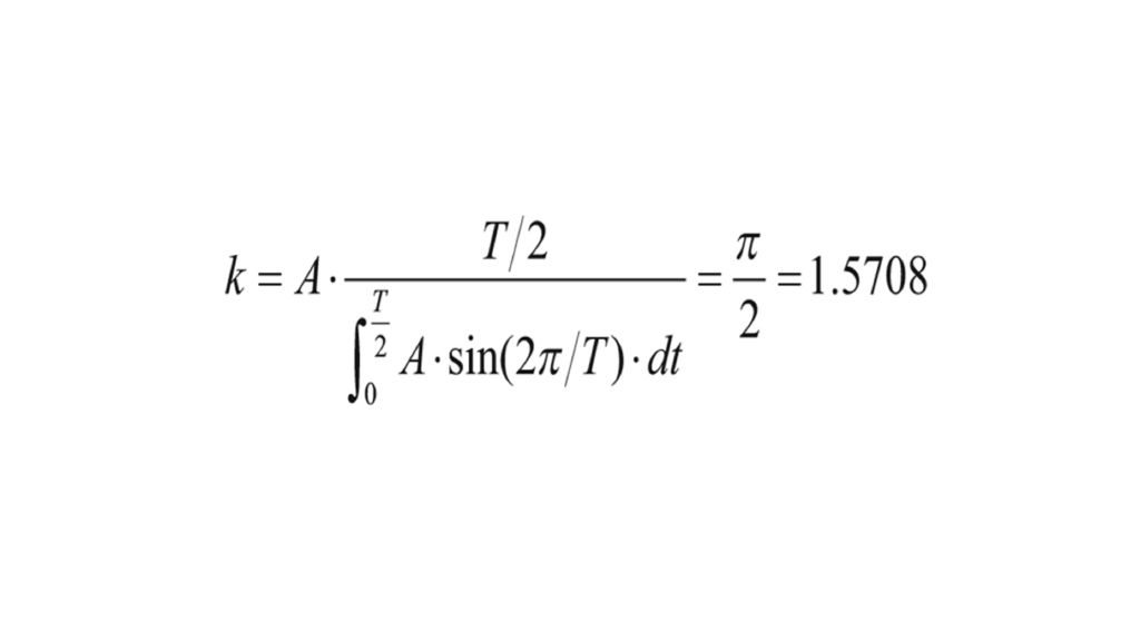
This pulse is analyzed by the R&S®RTO. Fig.2 shows the equation for the envelope in the R&S®RTO math function (formula editor), which uses the correction factor k= π/2.

For the best approximation of the envelope, the frequency of the lowpass filter has to be optimized. With a low cutoff frequency, ripples can be suppressed, but the settling process is slow. With a higher cutoff frequency, the settling process is faster, but more ripples are measured. In this example, a good compromise of fcut= 50 MHz for the cutoff frequency is used. With the known approximation trise= 0.35/fcut = 0.35/(50 MHz) = 7.0 ns, envelopes with rise times greater than 7.0 ns can be analyzed.

In Fig. 3, the yellow waveform is the modulated carrier wave and the black waveform represents the calculated, corrected envelope of the amplitude modulation.

The calculation in this measurement has a theoretical error of <1.5 % because the lowpass filter used is an approximation of the mean from the integral calculation. The calculated envelope is used to correctly measure the amplitude, rise/ fall time and pulse duration of the modulated pulse. The measurement result box “Meas Results 1” in Fig. 3 on the right shows the final measurements of the RF pulse.

The history mode is used to measure the PRI. This measurement is described in a separate application note (Application Note 1TD02 “Advanced Signal Analysis using the History Mode of the R&S®RTO Oscilloscope”; M. Hellwig, T. Kuhwald).

Summary

The R&S®RTO digital oscilloscope analyzes RF pulses up to the maximum bandwidth of the instrument used. The RF pulse analysis comprises the parameters frequency, PRI, pulse duration and rise/fall time. The calculated correction factor k is used to adjust the amplitude measurements of RF pulses in order to obtain the correct amplitude of the RF pulse envelope.

Zoom of the rising RF pulse flank with the corrected envelope added as black waveform.
Fig.3 Zoom of the rising RF pulse flank with the corrected envelope added as black waveform.

Related solutions