Interested?

R&S®Essentials | LCR meters fundamentals

Choosing the correct instrument: LCR meter vs. VNA

Author: Shivam Arora, Product Manager for Power Supplies and LCR meters

The LCR meter and the vector network analyzer (VNA) are two powerful instruments for RF and microwave engineering, each playing a crucial role in characterizing the electrical properties of components and devices. It can be difficult to know which one you need. But hey, don’t stress! Understanding the difference between these two instruments will help you pick the perfect one for your specific needs.

How do LCR meters work

LCR meters are used to evaluate the electrical properties of passive components like resistors, capacitors and inductors.

Here is a simplified explanation of how LCR meters work:

  • AC excitation: LCR meters apply an AC voltage or current signal to the device under test (DUT).
  • Voltage and current measurement: The LCR meter measures the voltage and current across the DUT.
  • Impedance calculation: Using the measured voltage and current values, the LCR meter calculates the impedance of the DUT.
  • Display and analysis: Calculated impedance values are displayed as numerical values, graphs or charts. You can interpret this data to understand the electronical characteristics of the DUT.
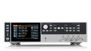
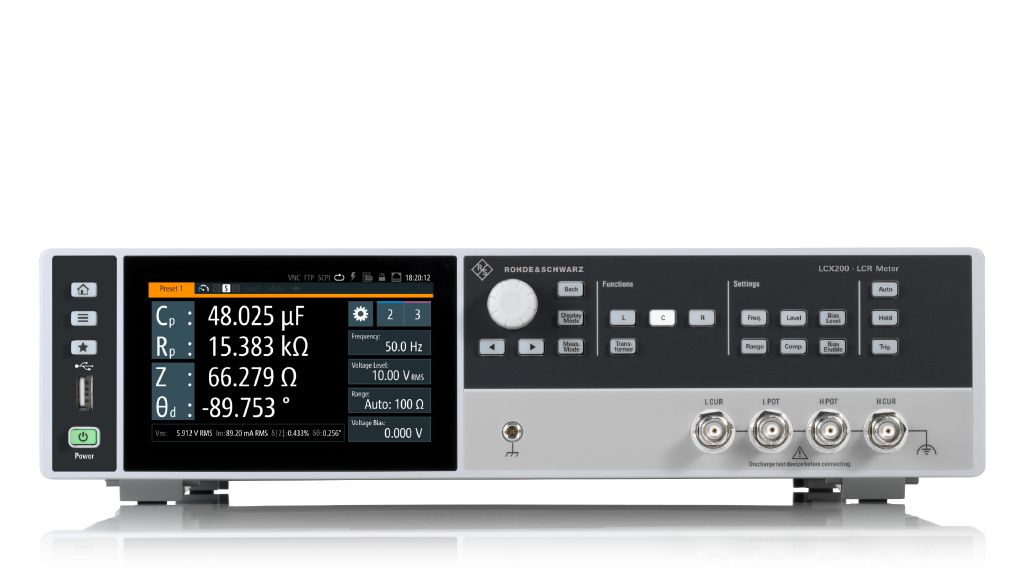
Display of the R&S®LCX LCR meter
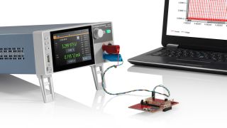
R&S®LCX LCR meter

LCR meter impedance measurement

LCR meters apply an AC signal to the DUT and measure the complex ratio of the resulting voltage and current. Using this information, they calculate the impedance of the DUT. The impedance is represented in rectangular form as:

Z = R + jX

where R is the resistance, and X is the reactance, which can be inductive (positive) or capacitive (negative). The phase angle (j) represents the phase difference between the voltage and current within the circuit.

LCR meter impedance measurement

VNA impedance measurement

Unlike LCR meters, VNAs are not specifically for measuring impedance. However, they are commonly used to indirectly measure the impedance of a DUT at high frequencies, when impedance matching and accurate characterization are crucial for proper functionality.

The VNA measures two key scattering parameters, known as S-parameters: S11, which represents the reflection coefficient at the DUT's input, and S21, which represents the forward transmission coefficient from port 1 to port 2. Using these parameters, the VNA calculates the impedance Z between the ports using three methods, depending on the applicable impedance range:

Shunt Measurement Configuration: Z= (Z0(1+S11))/(1-S11)

Shunt Through Measurement Configuration: Z= (Z0(S21))/(2(1-S21))

Series Through Measurement Configuration: Z= (2Z0(1-S21))/S21

where Z0 is the reference impedance of the VNA (usually set at 50 ohm).

The complex impedance Z can also be directly read from the network analyzer using the Smith chart.

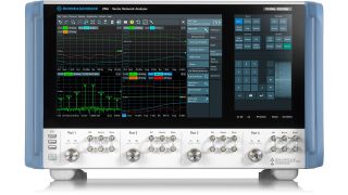
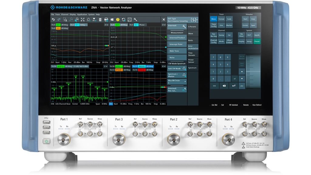
Display of the R&S®ZNA vector network analyzer
R&S®ZNA vector network analyzer
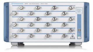
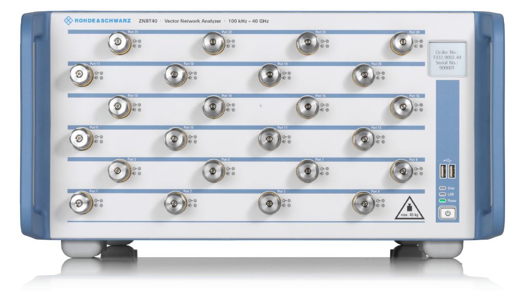
Display of the R&S®ZNBT Vector network analyzer
R&S®ZNBT Vector network analyzer
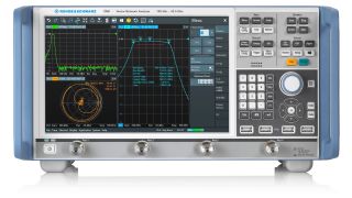
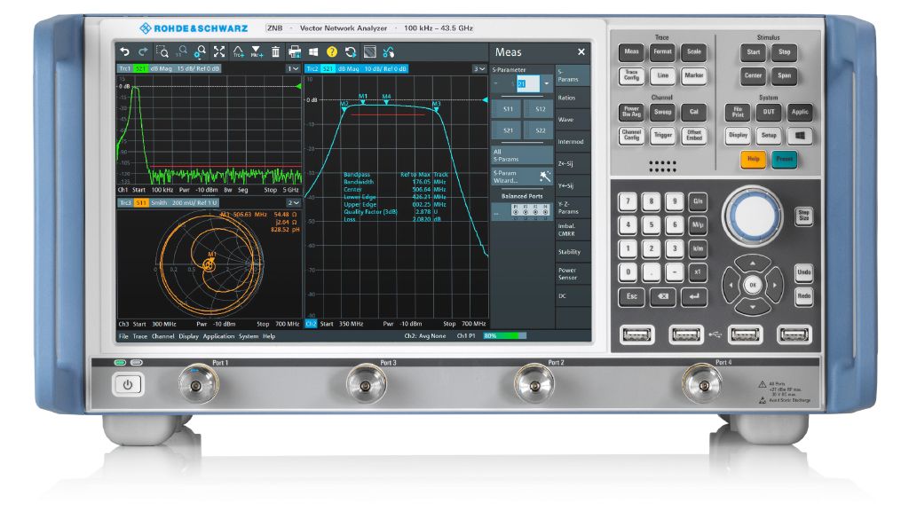
Display of the R&S®ZNB vector network analyzer
R&S®ZNB vector network analyzer
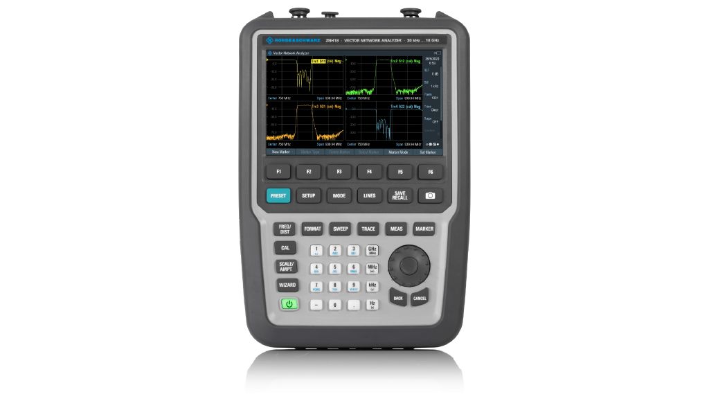
Display of the R&S®ZNH handheld vector network analyzer
R&S®ZNH handheld vector network analyzer

LCR meter vs. VNA - advantages and disadvantages

The main difference between an LCR meter and a VNA is that the VNA uses a fixed reference impedance (Z0). This makes VNAs more precise and allows them to be easily matched to the transmission lines. This impedance matching eliminates potential concerns such as parasitic inductance and capacitance.

In contrast, LCR meters can modify their reference impedance based on the DUT and other requirements. This means that they produce more accurate measurements, but it also means that the you need to compensate for the fixture and cables, which will eventually start behaving as parasitic elements.

VNAs measure S-parameters, which can then be converted to impedance parameters. The S-parameters are essential to understand the reflection, transmission loss and insulation of RF devices (e.g., a coupler) as well as to understand radiation properties (e.g., antenna). All of this means that the VNA is important when working in higher frequency ranges, from kHz to GHz. LCR meters, on the other hand, are restricted to impedance parameters and operate at a lower frequency range from DC to MHz.

Another point of comparison is the number of supported ports. VNAs can support multiple port devices such as couplers, but LCR meters can only support single port components such as resistors, capacitors and inductors.

Key differences between LCR meter and VNA

VNA LCR
Reference impedance 50 ohm Can be modified based on DUT
Frequency range kHz-GHz DC-MHz
Supported ports 1, 2, …N 1
Measured parameters Scattering parameters Impedance
Can derive other complex parameters Yes No
Examples of DUTs Couplers, antennas, etc. Resistors, capacitors, inductors
Price positioning Expensive Economical

Summary:

  • An LCR meter is used to measure the impedance of passive electronic components like resistor, capacitors and inductors.
  • A VNA is used to measure and characterize the behavior of high-frequency components and devices by analyzing their S-parameters.
  • LCR meters apply an AC signal to the DUT and measure the resulting voltage and current to calculate the impedance of the DUT.
  • VNAs measure two S-parameters, the reflection coefficient and the transmission coefficient, which it can use to calculate the impedance.
  • The main difference between the two instruments is that a VNA has a fixed reference impedance whereas the LCR meter can modify the reference impedance based on the DUT.
  • LCR meters are more accurate, and VNAs are more precise.

Are you interested in an LCR meter or a VNA?
Our experts will help you.

R&S®LCX LCR meter

R&S®LCX LCR meter

Key facts:

  • Frequency range upgradeable to 10 MHz
  • Basic accuracy of ±0.05 % for impedance measurements
  • Basic accuracy of ±0.03° for phase measurements
  • DC bias up to 40 V

Curious to learn more about test fundamentals?

Sign up for our newsletter