Our signal integrity test solutions
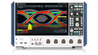
With R&S®RTO64 and R&S®RTP oscilloscopes, investigate the causes of the individual components of jitter with a new powerful method unique to R&S, supporting previously impossible measurements on individual jitter components and very short waveforms. Estimate the total jitter for a chosen bit error rate, or period of time.
With option K134 for R&S®RTO64 and R&S®RTP oscilloscopes investigate both jitter and noise, and the individual causes of either in high speed serial signals. The R&S method retains all signal data, as opposed to the conventional measurements.
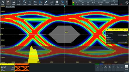
R&S®RTP options K136 and K137 introduce eye analysis in close to real time to detect both jitter and noise in high speed digital interfaces, such as USB, PCIe, MIPI, Ethernet or DDR. The eye is updated in close to real time for bit monitoring, and with the necessary speed to create eye diagrams for high speed digital interfaces with confidence in the validity of the eye.
Option K130 for R&S®RTO64 and R&S®RTP is a fully featured time domain reflection (TDR) and transmission (TDT) analysis system. Measure the reflection and the transmission of a fast pulse to characterize and debug signal paths, such as PCB traces, cables, and connectors. Display the resulting waveforms as impedance or reflection coefficients, over time or distance.
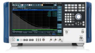
FSWP is a high precision phase noise tester, ideal for precise phase noise characterization of oscillators during development. Includes an optional spectrum analyzer and signal analyzer in a single box, for frequencies from 1 MHz – 50 GHz. R&S® FSWP is not only extremely fast and accurate, it is extremely easy to set up and use, too; run additive/residual phase noise and pulsed phase noise measurements at the touch of a button.
The R&S®FSPN is a dedicated phase noise analyzer and VCO tester for synthesizers, and VCO, OCXO, and DRO oscillators. R&S®FSPN has exactly the functions required at a suitable price for production test and design validation.
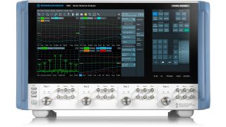
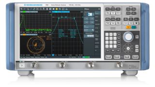
Calculate the insertion loss per inch of a signal trace on a PCB layer with functions fully integrated in the Rohde & Schwarz network analyzers, R&S®ZNA, R&S®ZNB, R&S®ZNBT and R&S®ZND as Option K231.
Particularly at higher data rates, vector network analyzers are increasingly replacing traditional time domain reflectometry (TDR) setups for testing passive components such as connectors, cables and PCBs. Benefit from the higher accuracy, and speed of the R&S®ZNB network analyzer for precise measurements on high-speed digital signal lines.
Very few modern consumer devices include an external interface suitable for connecting to a test instrument. Wireless communication devices can be tested over the air; for all others a test fixture is required to connect the device under test to the test instrument. Rohde & schwarz supply a wide range of test fixtures. As a test fixture has its own RF properties, these will affect the signal values measured. Rohde & Schwarz supply de-embedding functions to evaluate the impact of the test fixture on a test setup.
Investigating signal integrity issues requires waveforms to be sampled at locations throughout the device under test. Rohde & Schwarz supply all the necessary highspeed probes with a wide range of tips and other connectors, with high impedance and high bandwidth. The physical contact between a probe and the test point inevitably affects the electrical properties of the waveforms; Rohde & Schwarz supply functions to characterize and remove the influence of the probe from the measurements.


