Key Facts
- Modular, reliable and cost-efficient
- Compact, secure and flexible
- Powerful control and RF relay modules up to 67 GHz
- Expandable system configurations
- Convenient manual and remote control and trigger function



Key Facts
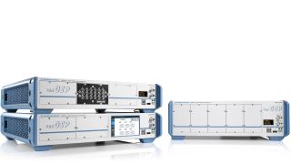
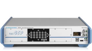
The R&S®OSP comes in two compact 2 HU models (R&S®OSP220, R&S®OSP230) and one large 3 HU model (R&S®OSP320) to meet diverse test scenario requirements – ranging from desktop configurations for laboratory measurements to complex, rack-integrated test systems.
The R&S®OSP230 model comes with a manual control touchscreen. The R&S®OSP320 model has a monitor option.
Quick Links
Essential for reproducible measurements
The modularity of the R&S®OSP family speeds up test and measurement configurations for applications in production, test labs and development. Implementing complex wiring with a single switch and control platform is essential for reliable and reproducible measurements that can be automated for cost-efficient test sequences.
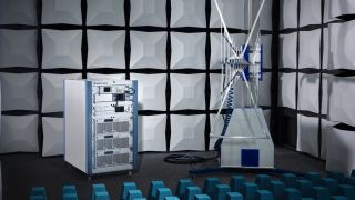
EMC test system with R&S®OSP
The R&S®OSP distributes generator and amplifier signals to multiplex forward and reverse signals and check interlock signals.
Different models in up to 10 flexible module slots
R&S®OSP units are accommodated in a compact 19" cabinet of two or three rack units.
The powerful CPU and LINUX operating system provide maximum flexibility for controlling switch and control modules, enabling use of internal and external interfaces.
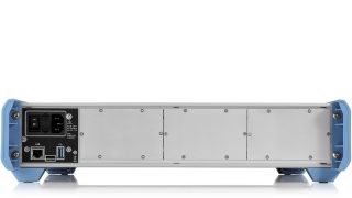
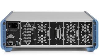
The module slots on the rear and front of each unit can be integrated into one, extra-wide triple or double module slot to accept larger modules with an extended range of functions.
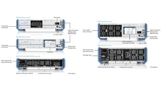
Front and rear view of the R&S®OSP220, R&S®OSP230 and R&S®OSP320 switch and control units
Detailed overview also available on page 10 of the product brochure.
Electromechanical relays up to 67 GHz
Options include:
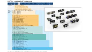
Overview of modules with RF coaxial relays
Easy system integration and virtually unlimited expandability
All R&S®OSP models can be combined via Ethernet in a local, corporate or global network with a primary/secondary configuration. Existing R&S®OSP systems can be expanded to meet future requirements.
The compact R&S®OSP‑B200S2 satellite box can be used for remote operation as an alternative to networking multiple R&S®OSP units. The satellite box moves RF switching and controlling closer to the DUT or antennas,. reducing the number of long RF cables required, improving RF performance of the setup and saving costs.
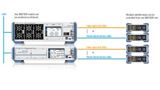
Possible OSP unit and satellite box combinations
Easy manual operation and remote control using web interface
R&S®OSP models come with a built-in web interface for local operation or remote control from a PC or laptop with browser. When control is browser based, the displayed content resolution is automatically adjusted to the monitor screen size.
All R&S®OSP models can be controlled with a keyboard and mouse and an external HDMITM monitor.
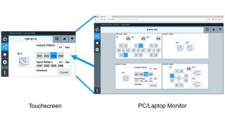
Web GUI for switching and path definition
Efficient manual operation or programming
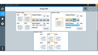
Path definition example for relays in different modules
Faster Switching
External triggers control switching processes more precisely and make them up to 1000 times faster when solid-state relays are used. Key trigger function features
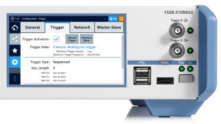
R&S®OSP unit with trigger interfaces on the front side.
The trigger menu shows the minimum trigger interval possible for the given path configuration
| Interfaces (front panel) | ||
| USB | for keyboard, mouse or USB stick | R&S®OSP220: 2 R&S®OSP230: 2 R&S®OSP320: 2 2 × USB 2.0, type A female connector |
| HDMITM | for external monitor | R&S®OSP220: 1 R&S®OSP230: 1 R&S®OSP320: 1 HDMITM female connector |
| Touchscreen | for manual operation | R&S®OSP220: - R&S®OSP230: 1 R&S®OSP320: 1) VGA, color |
| External trigger | input and output | R&S®OSP220: 2 R&S®OSP230: 2 R&S®OSP320: 2 BNC |
| Status display | display of TCP/IP address | R&S®OSP220: 1 R&S®OSP230: - R&S®OSP320: 1 b/w |
| 1) Optional, R&S®OSP-B300M touchscreen module | ||
| Interfaces (rear panel) | ||
| USB | R&S®OSP220: 1 R&S®OSP230: 1 R&S®OSP320: 1 USB 3.0, type A female connector |
|
| LAN | remote control via LAN | R&S®OSP220: 1 R&S®OSP230: 1 R&S®OSP320: 1 Ethernet RJ-45 female connector, 10/100 Mbit/s |
| Protected memory slot | Operating system | R&S®OSP220: 1 R&S®OSP230: 1 R&S®OSP320: 1 micro-SD card slot |
| Additional trigger interface | 4 bit | R&S®OSP220: - R&S®OSP230: - R&S®OSP320: 1 D-Sub 9 male |
| Environmental conditions | ||
| Temperature | Operating temperature range | 0 °C to +50 °C |
| Storage temperature range | –25 °C to +70 °C | |
| Damp heat | +40 °C, 90 %, rel. humidity, constant, in line with EN 60068-2-30 | |
| Height above zero | 0 to 4600 m | |
| Mechanical resistance | ||
| Vibration | Sinusoidal | 5 Hz to 55 Hz, 0.3 mm amplitude const., 55 Hz to 150 Hz, 0.5 g const., in line with EN 60068-2-6 |
| Random | 10 Hz to 300 Hz, acceleration 1.2 g (RMS) in line with EN 60068-2-64 | |
| Shock | 40 g shock spectrum, in line with EN 60068-2-27, MIL-STD-810E, method no. 516.4, procedure I | |
| Power supply | ||
| Rated voltage | 100 V to 240 V AC (± 10 %) | |
| Rated frequency | 50 Hz to 60 Hz (± 10 %) | |
| Max. input power | 1.5 A to 3.6 A (max. 310 VA) | |
| Rated power | Without modules | < 25 W |
| Dimensions (W × H × D) | ||
| R&S®OSP220, R&S®OSP230 | 444.7 mm × 107.6 mm × 471.9 mm (17.51 in × 4.24 in × 18.58 in) | |
| For rackmounting (without modules) | 1/1 19", 2 RU, depth 425 mm (16.73 in) | |
| R&S®OSP320 | 444.7 mm × 152.05 mm × 471.9 mm (17.51 in × 5.99 in × 18.58 in) | |
| For rackmounting (without modules) | 19" 1/1, 3 RU, depth 425 mm (16.73 in) | |
| Weight | ||
| R&S®OSP220 (without module) | approx. 6.85 kg (15.1 lb) | |
| R&S®OSP230 (without module) | Approx. 6.95 kg (15.3 lb) | |
| R&S®OSP320 (without module) | Approx. 7.95 kg (17.5 lb) | |
| Further information | ||
| Operating system: LINUX® | ||
| Certificates: EU (CE, RoHS), China, Canada, USA, Korea | ||

Numéro de commande 1528.3486.02
Hardware trigger function

Numéro de commande 1528.3128.02
Touchscreen module for R&S®OSP320

Numéro de commande 1528.3134K02
Satellite

Numéro de commande 1528.3134K04
Satellite

Numéro de commande 1528.3140.02
Remote Control Module

Numéro de commande 1528.3140.04
Remote Control Module
Numéro de commande 1528.3205.02
AC power supply for R&S®OSP-B200S2 satellite box (required for FOL interface)

Numéro de commande 1528.3170.02
Electrical bus cable, length: 5 m and 10 m

Numéro de commande 1528.3186.02
Fiber-optic link (FOL), SC-to-SC, length: 5 m to 40 m

Numéro de commande 1528.1690.04
Fibre-optic link (FOL), SC to FSMA, length 0,5m to 40m

Numéro de commande 1528.1702.04
Fibre-optic link (FOL), FSMA to FSMA, length 0,5m to 40m
Numéro de commande 1505.4763.02
Module Panel
with 12 x SMA mounting holes
Numéro de commande 1505.4770.02
Module Panel
with 4 x N mounting holes
Numéro de commande 1505.4534.02
Cable Set
4 x N(f) to N(f)
Numéro de commande 1505.4540.02
Cable Set
4 x N(f) to SMA(f)
Numéro de commande 1505.4557.02
Cable Set
4 x SMA(f) to SMA(f)
Numéro de commande 1177.8026.00
19" rack adapter, 2 RU for R&S®OSP220, R&S®OSP230
Numéro de commande 1177.8032.00
19" rack adapter, 3 RU for R&S®OSP320

Numéro de commande 1528.1590.02
SMA wrench for easier assembly of RF cables
8 mm wrench for RF cables with SMA to 1 mm connector (m), with knurled wheel for manual preassembly

Numéro de commande 1505.5601.02
RF Switch Module (double module width)
3 x SPDT (N), 0 Hz to 12.4 GHz, and 3 x SPDT (BNC), 0 Hz to 900 MHz

Numéro de commande 1505.4740.02
RF Switch Module
2 × SPDT (N), 0 Hz to 12.4 GHz

Numéro de commande 1505.4757.02
RF Switch Module
6 × SPDT (N), 0 Hz to 12.4 GHz

Numéro de commande 1528.3157.02
RF Switch Module
1 × SP6T (N), 0 Hz to 12.4 GHz, non-terminated

Numéro de commande 1522.4500.02
RF Switch Module
2 × DPDT (N), 0 Hz to 12.4 GHz

Numéro de commande 1505.5101.02
RF Switch Module
6 × coaxial changeover relays SPDT (SMA), 0 Hz to 18 GHz

Numéro de commande 1505.5101.52
RF Switch Module
6 × SPDT (SMA), 0 Hz to 18 GHz, latching

Numéro de commande 1505.5201.02
RF Switch Module
2 × coaxial multiposition relays SP6T (SMA), 0 Hz to 18 GHz

Numéro de commande 1505.5201.52
RF Switch Module
2 × SP6T (SMA), 0 Hz to 18 GHz, latching

Numéro de commande 1515.5827.02
RF Switch Module
2 × DPDT (SMA), 0 Hz to 18 GHz

Numéro de commande 1515.5856.02
RF Switch Module
1 × SP8T (SMA), 2 × SPDT (SMA), 0 Hz to 18 GHz

Numéro de commande 1515.5504.02
RF Switch Module
3 × SPDT (SMA), 0 Hz bis 18 GHz, terminated

Numéro de commande 1515.5510.03
RF switch module
1 x SP6T (SMA), 0 Hz to 18 GHz, terminated

Numéro de commande 1515.5527.03
RF switch module
6 x SPDT (SMA) and 1 x SP6T, 0 Hz to 18 GHz, terminated

Numéro de commande 1515.5533.03
RF switch module
3 x SPDT (SMA) and 1 x SP6T, 0 Hz to 18 GHz, terminated

Numéro de commande 1515.5540.03
RF switch module
6 x SPDT (SMA) and 3 x SP6T, 0 Hz to 18 GHz, terminated

Numéro de commande 1517.7004.02
RF Switch Module
1 × SP8T (SMA), terminated, 2 x SPDT (SMA), not terminated, 0 Hz to 18 GHz

Numéro de commande 1528.1625.11
RF Switch Module
1 × SP6T, 1 × SPDT, 0 Hz to 18 GHz

Numéro de commande 1505.4605.26
RF Switch Module
6 × SPDT (SMA), DC to 26.5 GHz, non-terminated

Numéro de commande 1528.1560.12
RF Switch Module
n × SP6T (SMA, up to 26.5 GHz), non-terminated, n = 1 or 2

Numéro de commande 1528.1625.23
RF switch Module
1 x SP6T, n x SPDT (SMA, up to 26.5 GHz), non-terminated, Order number: 1528.1625.2n, n = 1 to 3

Numéro de commande 1515.5827.26
RF Switch Module
2 × DPDT (SMA), DC to 26.5 GHz, non-terminated

Numéro de commande 1515.5856.26
RF Switch Module
1 × SP8T (SMA), 2 × SPDT (SMA), DC to 26.5 GHz, non-terminated

Numéro de commande 1515.5504.26
RF Switch Module
3 × SPDT (SMA), DC to 26.5 GHz, terminated

Numéro de commande 1528.1525.26
RF Switch Module
1 × SP6T (SMA), DC to 26.5 GHz, terminated

Numéro de commande 1515.5540.26
RF Switch Module
6 x SPDT (SMA) and 3 × SP6T (SMA), 0 Hz to 26.5 GHz, terminated

Numéro de commande 1517.7004.26
RF Switch Module
1 × SP8T (SMA), terminated, 2 x SPDT (SMA), not terminated, 0 Hz to 26.5 GHz

Numéro de commande 1528.3263.21
RF switch module
1 × SP6T (SMA), six additional connectors for external termination.

Numéro de commande 1505.4605.46
RF switch module
n x SPDT (2,92 mm), non-terminated, Order number: 1505.4605.4n, n = 3 to 6

Numéro de commande 1528.1560.42
RF switch module
n x SP6T (2,92 mm), non-terminated, Order number: 1528.1560.4n, n = 1 or 2

Numéro de commande 1528.1625.43
RF switch module
1 x SP6T, n x SPDT (2,92 mm), non-terminated, Order number: 1528.1625.4n, n = 1 to 3

Numéro de commande 1515.5827.40
RF Switch Module
2 × DPDT (2.92 mm, K), 0 Hz to 40 GHz

Numéro de commande 1515.5504.40
RF Switch Module
3 × SPDT (SMA 2.92, K), 0 Hz to 40 GHz, terminated

Numéro de commande 1528.1525.02
RF Switch Module
1 × SP6T (K (2.92 mm), 0 Hz to 40 GHz, terminated

Numéro de commande 1515.5540.40
RF Switch Module
6 x SPDT (2.92 mm) and 3 × SP6T (2.92 mm), 0 Hz to 40 GHz, terminated

Numéro de commande 1505.4605.56
RF Switch Module
n × SPDT (2.4 mm), non-terminated, n = 3 or 6

Numéro de commande 1528.1531.16
RF Switch Module
n × SPDT (2.4 mm), non-terminated, latching, n = 3 or 6

Numéro de commande 1528.1548.11
RF Switch Module
1 × SP6T (2.4 mm), 0 Hz to 50 GHz, latching

Numéro de commande 1528.1560.52
RF Switch Module
n × SP6T (2.4 mm), non-terminated, n = 1 or 2

Numéro de commande 1528.1625.53
RF switch module
n x SP6T (2,4 mm), non-terminated, Order number: 1528.1625.5n, n = 1 or 3

Numéro de commande 1515.5827.52
RF Switch Module
n × DPDT (2.4 mm), non-terminated, n = 1 or 2

Numéro de commande 1515.5504.53
RF switch module
n x SPDT (2,4 mm), terminated, Order number: 1515.5504.5n, n = 1 to 3

Numéro de commande 1528.1525.51
RF Switch Module
1× SP6T, (2.4 mm), 0 Hz to 50 GHz, internal termination

Numéro de commande 1505.4605.66
RF switch module
n x SPDT (1,85 mm), non-terminated, Order number: 1505.4605.6n, n = 1 to 6

Numéro de commande 1515.5991.16
RF Switch Module
n × SPDT (1.85 mm), non-terminated, latching, Order number: 1515.5991.1n, n = 3 or 6

Numéro de commande 1528.1654.63
RF switch module
n x SPDT (1,85 mm), terminated, latching, Order number: 1528.1654.6n, n = 1 to 3

Numéro de commande 1528.1560.61
RF switch module
1× SP6T, (1.85 mm), 0 Hz to 67 GHz, Order number: 1528.1560.61, n = 1 or 2

Numéro de commande 1528.1760.61
RF switch module
1 × SP6T (1.85 mm), terminated, latching, order number: 1528.1760.61

Numéro de commande 1505.5901.02
RF Switch Module
6 × SPDT (SMA), SSR, 9 kHz to 6 GHz, reflective

Numéro de commande 1505.4728.02
RF Switch Module
6 × SPDT (SMA), SSR, 9 kHz to 10 GHz, absorptive

Numéro de commande 1505.4734.13
RF switch module
n x SP6T (SMA). SSR. 9 kHz to 10 GHz, absorptive 23, Order number: 1505.4734.1n, n = 1 to 3

Numéro de commande 1505.4792.03
RF Switch Module
3 × DP3T (SMA), 10 W power SSR, 9 kHz to 8 GHz, reflective, term. SPDT versions, Order number 1505.7292.1n, n= 1 to 3

Numéro de commande 1528.1677.46
RF switch module
n x SPDT (2.92 mm), SSR, 9 kHz to 43.5 GHz, absorptive, order number 1528.1677.4n, n = 2, 4 or 6

Numéro de commande 1528.1660.44
RF switch module
n x SP4T (2.92 mm), SSR, 9 kHz to 43.5 GHz, absorptive, order number 1528.1660.4n, n = 2, 3 or 4

Numéro de commande 1528.1577.44
RF attenuator module
n x RF attenuator (2.92 mm), 9 kHz to 40 GHz, 4-Bit, 0 to 30 dB, 2 dB step, order number 1528.1577.4n, n = 2 or 4

Numéro de commande 1515.5985.02
Passive module
For integrating one R&S®NRP power sensor unit (with USB interface)

Numéro de commande 1505.5301.02
Digital I/O Module
16 × digital inputs, 16 × digital outputs

Numéro de commande 1505.5401.02
Relay driver module,
control of four external RF power relays, additional digital inputs/outputs, interlock

Numéro de commande 1505.5718.02
Multiplexer module
6-channel, 4-wire multiplexer

Numéro de commande 1505.4711.02
EMS Module (interlock with SPDT, digital I/Os)
for small systems with 1 × DPDT (N), digital inputs/outputs, interlock with SPDT

Numéro de commande 1528.3257.02
Module kit for the R&S®OSP320
The R&S®OSP-BCST is not pre-installed and is not mounted on the R&S®OSP320 base unit. Delivery expected from January 2025, subject to change without notice.

Numéro de commande 1528.3270.02
Load unit, 2 RU
Manufacturer's recommended retail price (MSRP). The price shown does not include VAT. Prices and offers are only intended for entrepreneurs and not for private end consumers.
You may use the electronic signature via DocuSign to submit your information to enroll with the Rohde & Schwarz Customer Delegated Administration program. DocuSign processes the information provided according to their . The minimum system requirements for using the DocuSign system may change over time. The current system requirements are found
Termes & Conditions du tirage au sort relatif aux 10 ans des oscilloscopes Rohde & Schwarz
1. Le tirage au sort “10 years Rohde & Schwarz oscilloscopes” est organisé par Rohde & Schwarz GmbH & Co. KG, Mühldorfstraße 15, 81671 Munich, Allemagne, Tel. +49 89 41 29 0 (référencé ici par “R&S").
2. Tous les participants peuvent s'inscrire au tirage au sort du 01 janvier 2020 au 31 décembre 2020 avec leur nom, le nom de leur entreprise et leur courriel professionnel.
3. La participation est gratuite et ne dépend pas de l'achat de biens ou de services.
4. Le tirage au sort est uniquement ouvert aux entités juridiques et seules les personnes morales peuvent gagner les prix. Une personne physique n'est pas autorisée à participer en son nom propre et pour son propre compte, mais en tant que représentant d'une entité juridique en remplissant le formulaire de participation au nom et pour le compte de l'entité juridique.
5. Les prix à gagner sont 1 des 10 R&S®RTB2000 au cours de la période allant du 1 janvier 2020 au 31 décembre 2020 :
Prix : 1x oscilloscope numérique R&S®RTB2000
6. Le tirage au sort aura lieu au siège social de Rohde & Schwarz, Muehldorstrasse 15, 81671 Munich. Les gagnants des prix seront informés par courriel sous 5 jours ouvrés.
7. Le représentant autorisé de l'entité juridique devra informer Rohde & Schwarz qu'il accepte le prix. En cas de refus d'acceptation, ou sans aucune réponse dans les deux semaines, un nouveau gagnant sera tiré au sort. Si aucun gagnant ne se manifeste sous quatre semaines, le tirage au sort prend fin et le prix est perdu.
8. Les employés R&S et les membres de leurs familles, ainsi que toute personne participant au processus du tirage au sort et les membres de leurs familles sont exclus du formulaire de participation.
9. Aucun équivalent en argent ou échange de prix n'est autorisé. Les prix ne sont pas transférables. Tous les impôts, les prélèvements, les droits, les taxes et toutes autres charges perçus dans le pays du participant sont à la charge du participant.
10. Les données personnelles seront traitées uniquement dans le cadre de ce tirage au sort et supprimées quatre semaines après celui-ci, sauf indication contraire.
11. Tout participant qui ne respecte pas ces Termes & Conditions peut être disqualifié par Rohde & Schwarz de ce concours. Dans un tel cas, les prix peuvent également être retirés de manière rétroactive. Dans le cas où un prix est retiré de manière rétroactive à cause du non-respect de ces conditions, il devra être retourné par le participant en question à ses frais à l'adresse Rohde & Schwarz mentionnée au point n°1 et un nouveau gagnant sera tiré au sort.
12. Les participants ne peuvent pas réclamer les prix de ce tirage au sort et aucune procédure juridique n'est autorisée à cet égard.
13. Le tirage au sort et toute relation contractuelle qui en découle entre Rohde & Schwarz et le participant respectif sont régis et interprétés conformément aux lois de l'Allemagne, sans aucun recours au conflit de lois. Les tribunaux de Munich, Allemagne, sont seuls compétents en cas de litige émanant directement ou indirectement de la participation à ce concours.
* “fast delivery” inside 7 working days applies to the Rohde & Schwarz in-house procedures from order processing through to available ex-factory to ship.


