Written by Meik Kottkamp | August 29, 2022


Introduction
The well-known 5G requirements triangle includes the ultra-reliable, low latency (URLLC) use case, generally associated with automotive and industrial applications. The question remains whether real-life networks deployed today do perform (mainly in terms of latency and reliability/availability of data services) as intended by 3GPP based on its simulated performance results. Globally, 5G NR networks are widely deployed, mostly based on the 5G non-standalone (NSA) architecture. In private campus network deployments, we note a strong desire for and partial realization of 5G standalone (SA) architectures.
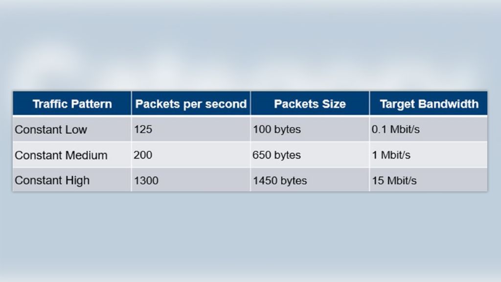
This article contains measurement results for both one-way latency (OWL) and round trip time (RTT) delays in a commercially deployed public 5G NSA network. Results were obtained using the commercially available interactivity test based on the QualiPoc Android solution for RTT from Rohde & Schwarz. For OWL, we used a prototype solution with GPS resources connected at the transmitting and receiving ends, again based on Qualipoc Android. The solution enables various data rates of 100 kbps, 1 Mbps and 15 Mbps. As expected, we observed superior 5G NR performance compared to LTE, although most of the improvements are in the cellular uplink (UL) direction. Best case 5G NR measurements revealed less than 7 ms OWL in DL for a 100 kbps service. Worst case 5G NR measurements showed around 18 ms OWL in UL for a 15 Mbps service.
All measurements were performed around the Rohde & Schwarz site in Munich, Germany. We used a Samsung S20 device, the QualiPoc Android measurement solution and a commercial Deutsche Telekom SIM card that allows access to LTE and 5G services.
The QualiPoc Android based solution enables data streams to be sent with the traffic characteristics shown in Table 1.
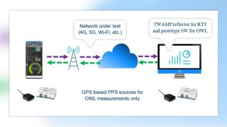
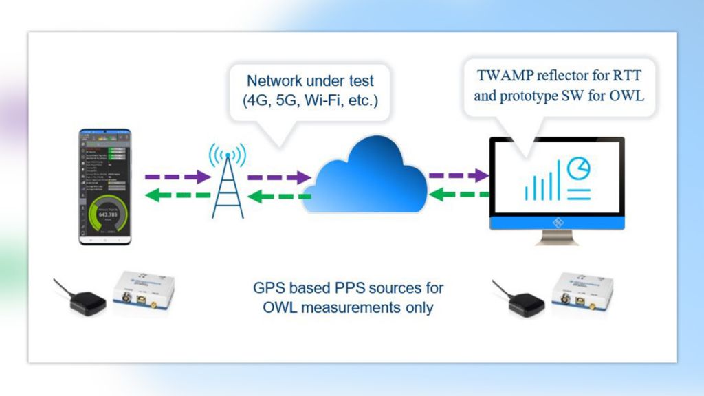
The packets sent from the device are received and immediately reflected by a server using the two-way active measurement protocol (TWAMP) specified in IETF RFC 5357. The TWAMP server is located in a Rohde & Schwarz office and accessible with a public IP address. The test solution is illustrated in Fig. 1 below. Note that although the focus of our campaign was LTE and 5G NR latency performance, the solution is agnostic to the underlying wireless technology.
Fig. 1 also illustrates the prototype solution for OWL measurements. In this case, dedicated software on the server and the device is used. Furthermore, additional GPS sources at the transmitting and receiving ends provide the pulses per second (PPS), which is used during pre-synchronization and the actual measurement phase. Consequently, the OWL test duration is increased compared to the fast interactivity test duration. In order to ensure a fair comparison of RTT and OWL results, we concentrated on stationary tests, i.e. scouted specific test locations and subsequently executed stationary tests at these locations.
Cellular networks and measurement campaigns
Our primary aim was to carry out one-way latency (OWL) and round trip time (RTT) measurements in the 5G NR network. We initially wanted to get a rough idea of where 5G NR network coverage was available. We therefore started our measurement test phase by hunting 5G bands, i.e. n1 and n78.
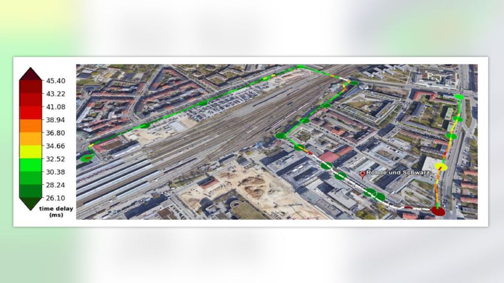
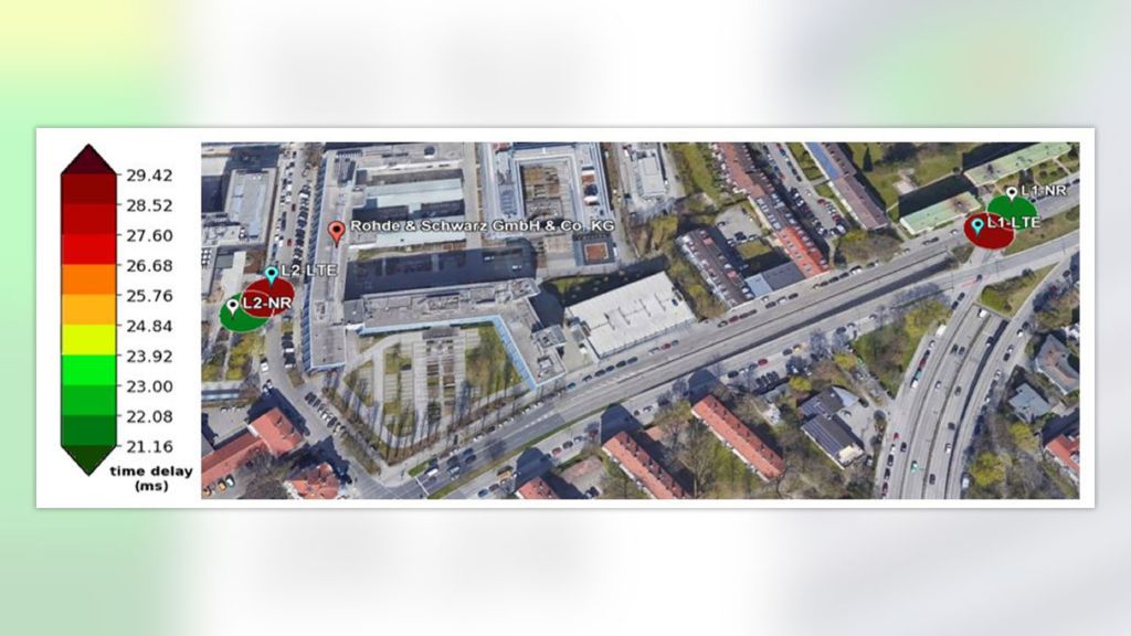
We used the QualiPoc functionality for band hunting, since it provides information related to network technology as well as the band of the signal received at a given moment and location. During our test phase, we also took some RTT measurements (see Map 1) to get a rough idea of how RTT performs under different traffic conditions (low, medium and high) in a 5G NR network.
In Map 1, we show mobile RTT measurements (illustrated by the path) and multiple stationary RTT measurements (illustrated by circles). The colors show the latency performance. It is interesting that for the mobile RTT measurements, we get outliers (white), which correspond to values with a mean RTT of over 100 ms.
On the contrary, while performing stationary RTT measurements, we got some of the best latency performance results close to or even at these locations. Although it is apparent that this phenomenon requires further investigation, we continued to proceed with only performing stationary measurements. As mentioned before, an additional argument in favor of stationary measurements is different measurement times for OWL and RTT measurements. After the scouting, we continued with measurements at various locations and conducted low, medium and high data rate cases for both RTT and OWL.
Results
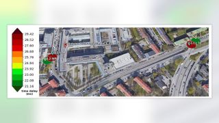
In the interest of the readers’ time, we have provided measurements results for two locations. These enabled both LTE and 5G NR measurements due to band forcing and they provided stable results (see Map 2 below).
The results are illustrated in the form of box plots. They are a great way of illustrating the distribution of our data and not just the central tendency (i.e. median, mean and mode), and additionally show how the data is spread. The goal of this representation is to show how the latency performance compares between the different locations by comparing the variance of the corresponding data sets as well as their median values.
In the result, we included the summation of the individual OWL on the UL and DL (UL+DL) for comparison with the respective RTT measurements. For the comparison, we found it worthwhile to merge all our NR data samples (L1-NR, L2-NR) and all our LTE data samples (L1-LTE, L2-LTE), thus creating a large data set of measurements obtained during various times of day and on various days during a week for a period of about a month. These overall results are shown in Figs. 2 and 3.
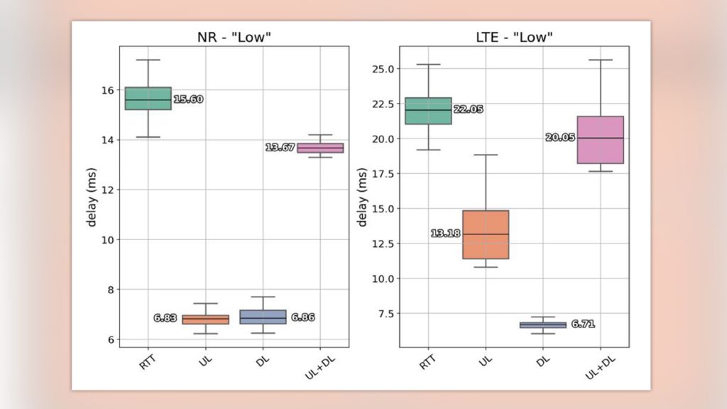
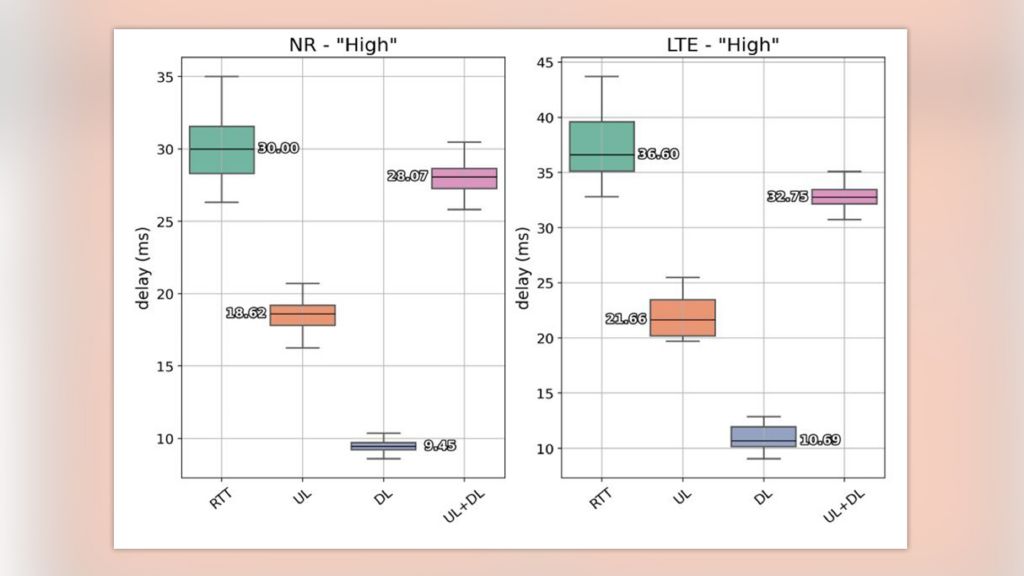
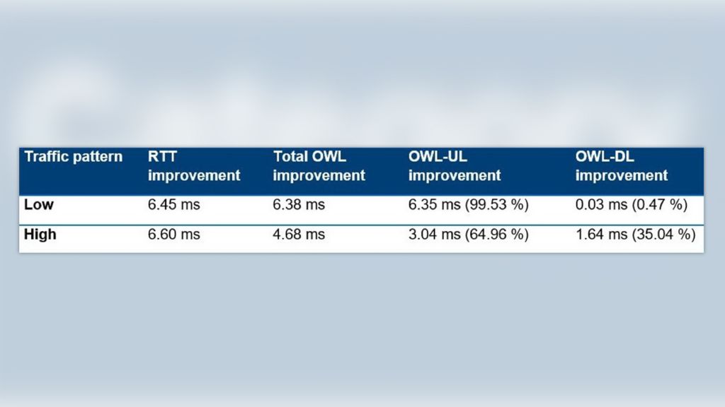
Table 2 summarizes the latency performance improvement for 5G NR compared with LTE for all traffic patterns.
Cellular networks and measurement campaigns
After discussing our measurement results, we had several conclusions:
1. In general, latency in the UL direction is higher than in the DL direction
2. The improvement in OWL latency from 5G is predominantly in the UL direction
3. In the high traffic load pattern, there was less overall OWL improvement compared to the RTT improvement
4. We noticed more improvement in the DL direction as the traffic load increased
5. The RTT measurements are consistently higher compared to the sum of OWL-UL and OWL-DL due to the reflecting server
The analysis illustrates results in an example commercial network, with measurements taken in Munich in summer and fall 2021. 5G NR network deployment is obviously an ongoing process, which may result in improvements due to increased coverage and additional capacity. We believe that latency performance is of particular interest for private 5G NR deployments, specifically if a private 5G network is used in an industrial environment to support use cases such as process automation, mobile robots, AGVs and remote control of automation equipment. In these deployments, we expect higher flexibility to adapt network settings to the applications.
The test method is further described in the following white paper:
White paper "Interactivity test"
We will continue our measurement campaign in private 5G networks and intend to present the results in a similar blog entry in the future.


