Mobile network testing blog

Stories & insights

Mobile network testing

Written by Arnd Sibila | June 12, 2018

5G: Initial 5GTF coverage measurements (part 2)

The US operator Verizon Wireless targets fixed wireless access (FWA) in the 28 GHz frequency band. With partners, they created a pre-5G specification called 5G Technical Forum (5GTF). The business case depends on the number of households that can be connected to a certain number of base stations and still provide a suitably high data throughput. For the required signal quality and 5G coverage measurements, Verizon Wireless trusted our prototype measurement backpack solution.

5GTF coverage

Pre-5G versus 5G

To define a “one fits all” technology within a standardization body, such as 3GPP, can be very time-consuming. Hundreds of companies and organizations voice their ideas and recommendations on how to address the specific 5G challenges and requirements. Proposals are discussed and evaluated repeatedly, before finally making a decision on how to proceed.

Often, a particular application is addressed and a specification targeting only one scenario is developed. Fixed wireless access (FWA) is one of the applications supported in the ongoing 5G discussions.

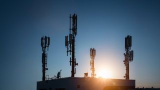
Verizon targets FWA in the 28 GHz frequency band. The U.S. telecommunications regulator FCC allocated the band with a bandwidth of up to 850 MHz as 5G spectrum in 2016. Verizon obtained 28 GHz licenses through the acquisition of XO Communications in 2015 and plans to use them for the initial rollout of its own pre-5G standard: the 5GTF. The specification was co-created with Korean operators and other industry players from the infrastructure, chipset and device side and published in June 2016.

With FWA, Verizon aims to overcome the higher path loss in the 28 GHz band. Since the application is designated for customer premises equipment (CPE), mobility is neither targeted nor specified. The focus is on providing high user data rates that can compete in the fixed network area.

28 GHz creates high frequency challenges

Analyzing the free space propagation loss (FSPL), path loss increases as frequency increases. Wavelength (λ) and frequency (f) are connected through the speed of light (c). In other words, with λf = c, frequency increases as wavelength decreases. This has two major effects and challenges:

  • The first effect relates to propagation. Below 6 GHz, diffraction is typically the dominating factor affecting propagation. At higher frequencies, the wavelengths are so short that they interact more with surfaces. As a result, their scattering and reflection have a much greater effect on coverage. At 28 GHz the path loss for line-of-sight (LOS) is much higher than below 6 GHz. FWA often encounters non-line-of-sight (NLOS) situations that are even more critical concerning path loss.
  • The millimeter wave (mmWave) spectrum challenges mobility. The higher the carrier frequency (and the higher the desired velocity that the system should support), the higher the Doppler shift and the lower the Channel Coherence Time (the time that the receiver can use for the equalization process). The use of centimeter wave (cmWave) and mmWave frequencies in high mobility scenarios is inefficient or unfeasible. With FWA, mobility is not required, so Verizon’s technology approach can completely rely on mmWave frequencies, together with the exchange of control and signaling information between the network and connected device.
Decreasing wavelengths have a positive effect that may help to overcome the higher path loss.
  • With decreasing wavelengths the required spacing between two antenna elements (usually λ/2) decreases. This enables the design of practical antenna arrays with multiple antenna elements. The higher the order of the array, the better the focus of transmitted energy in a specific direction (beamforming). This allows the system to overcome the higher path loss experienced at cmWave and mmWave frequencies. This effect can be exploited in base stations but also in user devices such as CPE in the case of Verizon’s FWA approach.

The specification 5GTF defines a simple beamforming scheme. Depending on the selected beamforming reference signal (BRS) transmission period, multiple beams can be transmitted. The CPE performs signal quality measurements on the BRS. Based on the BRS received power (BRSRP) measurements, the CPE will maintain a set of the eight strongest beams and report the four strongest ones back to the network.

3GPP initially focused the standardization of 5G new radio (5G NR) in the non-standalone (NSA) mode. NSA uses LTE as the anchor technology for the exchange of control and signaling information and for mobility.

Prototype for 5G coverage measurements

The most interesting parameter in mobile networks is coverage. This is especially true when networks operate in high frequency bands such as 28 GHz. There, the signal propagation is difficult and not yet fully understood.

In view of the highly competitive timeline for early 5G adopters, Rohde & Schwarz mobile network testing designed a prototype measurement system that uses an ultra-compact drive test scanner that covers frequency bands up to 6 GHz.

This frequency range is extended by using a down-conversion approach. This means that up to 8 100-MHz-wide component carriers transmitted at 28 GHz are down converted to an intermediate frequency range that drive test scanners can process.

R&S 5GTF prototype
The R&S 5GTF prototype measurement system’s setup and components
Open Lightbox

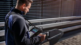
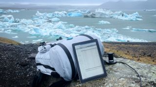
The entire solution is integrated into a battery-operated backpack, enabling coverage measurements in the field, for example, in office buildings. Verizon used the 5GTF prototype measurement backpack in a trial network in the second half of 2017.

The screen shot below shows an example of the measurement results processed with R&S®ROMES4. It displays the plotting of the eight strongest beams of all detected carriers (PCI), including the discovered beam index. The beams are organized based on the best carrier-to-interference and noise ratio (CINR) measured for the BRS, rather than BRSRP. At the top of the screen, the user can enter a particular PCI and identify the eight strongest beams for that carrier at the actual measurement position.

visual plotting to determine strongest beam index
Visually appealing plotting facilitates determining the strongest beam index.
Open Lightbox
Conducting 5G coverage measurements
Conducting 5G coverage measurements with the 5GTF prototype measurement backpack
Open Lightbox

The next post in our 5G blog series will discuss the Signals Research Group activity in testing Verizon Wireless’ 5GTF trial networks in the US using the Rohde & Schwarz prototype backpack solution.

Stay tuned!

Read part 1 of the 5G series “The role of mobile network testing on the path to 5G” and learn how 5G represents a paradigm shift in the development process of the next generation of mobile communications.

Related stories

5G site testing and troubleshooting mobile networks

Read more

5G: First independent 5G test network benchmark study (part 3)

Read more

Testing 5G QoE: Use cases, services and a new QoE paradigm (part 1)

Read more

Subscribe MNT blog

Sign up for our newsletter

Stay up to date and get stories and insights with our frequent mobile network testing newsletter.

Stories by category

Benchmarking & optimization

More information

Field services & interference hunting

More information

Innovations in mobile network testing

More information

Testing from RF to QoE

More information

Request information

Do you have questions or need additional information? Simply fill out this form and we will get right back to you.

Marketing de permission

Votre demande a bien été envoyée ! Nous vous contacterons dans les plus brefs délais.
An error is occurred, please try it again later.