Written by Manuel Mielke | January 14, 2021


Why is network synchronization necessary?
Let’s look back on 2G (GSM). Moving between cells means handing over from one cell to another. To avoid dropped calls, assigned time slots have to be met, and the center frequency of the carrier needs to be accurate enough for the mobile phone to synchronize on it.
About a decade later, and with the rollout of LTE-TDD, network synchronization became an even stricter requirement. The LTE resource grid, where uplink and downlink traffic is scheduled, offers even less room for time and frequency deviations: For LTE-TDD, the network synchronization requirement is in the range of microseconds in the time domain and a few Hz in the frequency domain.
Reasons for rigorous 5G NR synchronization requirements
From a specification perspective, 5G NR is exceptionally flexible. It can be implemented in either standalone (SA) or non-standalone (NSA) mode (in NSA, the control plane and uplink are done on LTE). Furthermore, traffic scheduling is very adaptable, enabling FDD and TDD operation modes to combine into a multimode network; FDD or TDD can be selected based on efficiency, depending on channel conditions. With such architecture and scheduling flexibility, rigorous network synchronization requirements are given in 5G NR.
Impact of time-synchronization on the network
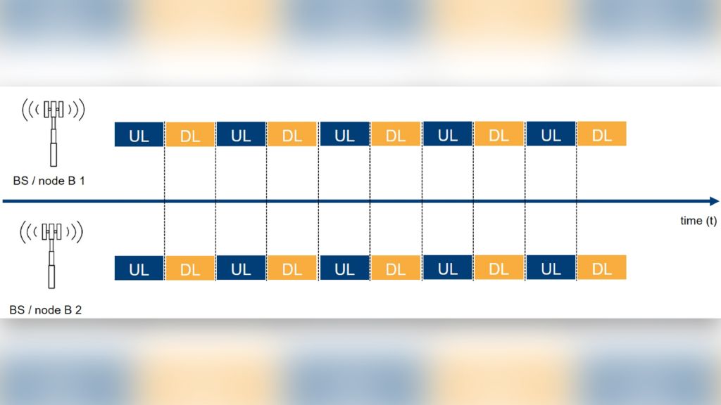
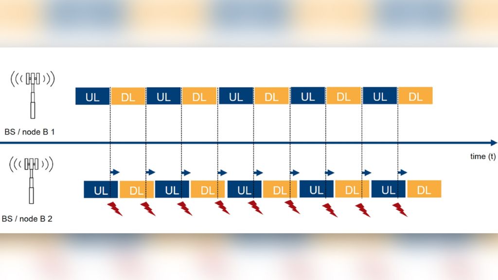
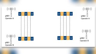
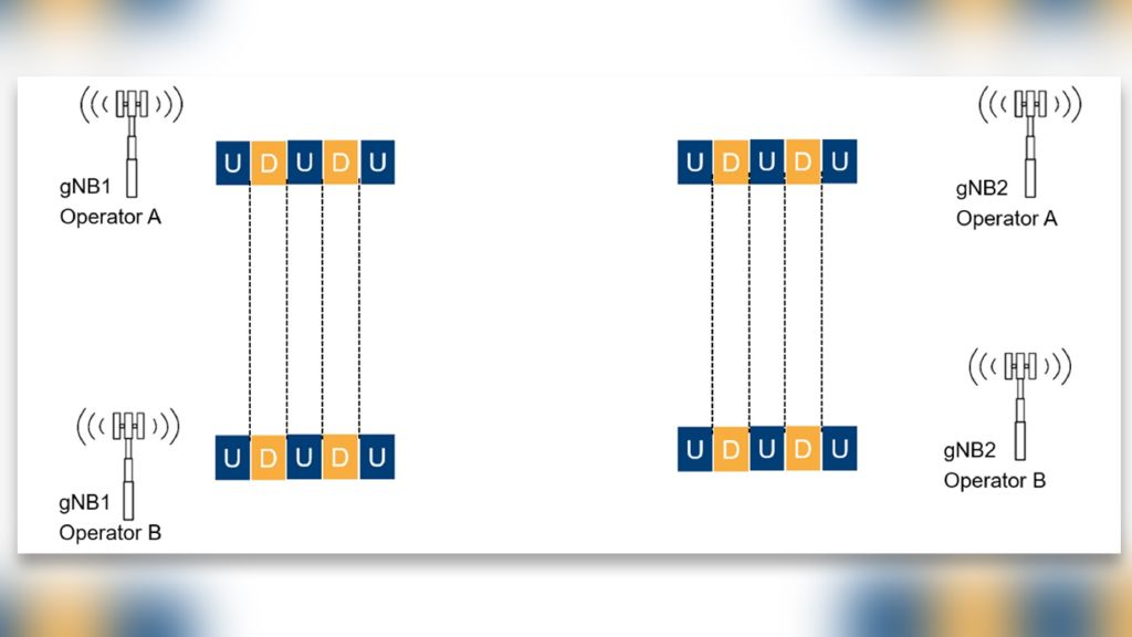
Let’s compare and contrast. In the image gallery below, you will find two illustrations: Figure 1 depicts a perfectly time-synchronized TDD network with two cells in the time domain; figure 2 shows the same TDD network with a time delay in one of the cells.
Comparing the figures shows that in the perfectly time-synchronized TDD network (figure 1), the uplink and downlink timeslots on the time domain are in sync. In figure 2, with the added time delay, parts of the uplink and downlink timeslots are now interfering with each other, having a negative impact on network performance in the time domain. But what about time synchronization between different networks operating on different frequencies?
Network synchronization between operators
Networks of different operators typically operate on different frequencies. What happens if (passive) interference occurs? Interference always means unwanted ghost carriers in the spectrum, increasing the probability that the ghost carrier of network 1 interferes with the “real” carrier of network 2. If that is the case, the result looks like in figure 2 in the image gallery above.
Let’s assume operator B’s network creates interference. If both networks are properly time-synchronized, the uplink slots remain clean. Only the downlink might be affected, depending on the interfering ghost carrier’s strength. We call this a “limitation of possible loss”, which is one reason why more and more countries are defining requirements on the time-synchronization between networks of different operators.
How to measure network synchronization in the time domain
Network synchronization measurements are over-the-air (OTA) measurements. Therefore, when a signal sequence arrives at the receiver, the point in time is a perfect measure for network synchronization on the time domain. So-called time-of-arrival values need an accurate reference point in time.
One of the most accurate time sources is the pulse-per-second (PPS) signal from a Global Navigation Satellite System (GNSS) receiver. Depending on the GNSS signal and receiver quality, 30 ns accuracy is possible. Receivers, such as the R&S®TSME6 scanner, that can decode both 5G and GNSS signals provide the arrival time of the 5G (or LTE) sequence and calculate its offset from the PPS pulse. This provides extremely accurate and highly reliable time-of-arrival data.
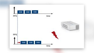
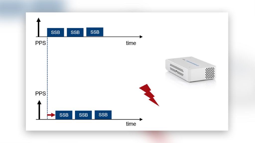
Given 5G NR and time accuracy in the range of tens of ns, the distance between the transmitter and receiver is of great significance, as time-of-arrival measurement values depend on the time it takes for the signal to travel between the transmitter and receiver. When comparing time-of-arrival values, always remember the impact of distance: electromagnetic waves travel with the speed of light, 1µs = 1000 ns = 300m.
Let’s look at some time-of-arrival (TOA) results from 5G NR field data. TOA/PPS is measured for each PCI/SSB combination. When interpreting the values, we need to remember that SSBs are transmitted subsequently over time. Therefore, when comparing time-of-arrival values, make sure that you compare simultaneously transmitted SSBs (in figure 3 below, this corresponds to the lighter and darker shades of the same color).
Most likely, such SSBs have the same SSB index. If not, you will end up with a difference of 200+ µs, which is the time difference between the starting symbols of the SSB as specified by the 3GPP. The illustration below shows comparable time-of-arrival values from the TopN list in R&S®ROMES4 with several SSBs of the same color in different shadings.
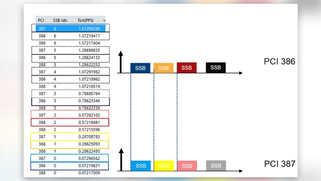
Time-of-arrival measurements can be performed on any received SSB, regardless of channel or operator. This allows using the measurement solution for time-of-arrival measurements on several channels from different operators.
In part 2 of the network synchronization article series, I will explain how synchronization in the time domain affects the frequency domain and how time delays in the signal path from the baseband to the receiver can be identified.


