Written by Corbett Rowell | November 1, 2022
5G mobile network testing using a passive network scanner (Part 4)
Network synchronization of 5G networks

Written by Corbett Rowell | November 1, 2022
Network synchronization of 5G networks


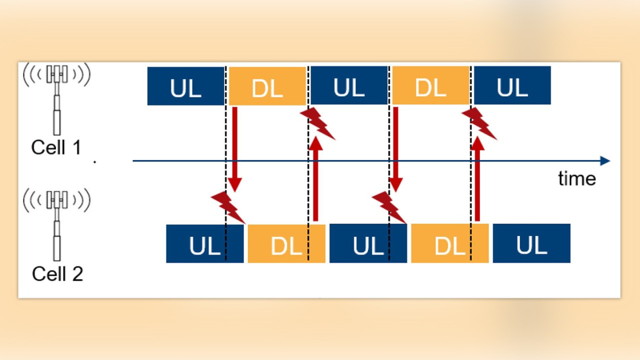
Ensuring the base station synchronization is a critical component for successful network deployment. If a base station is out-of-sync, the handover of active connections will fail, leading to dropped calls for the user and a poor user experience. For TDD the synchronization requirement is particularly crucial as a time offset can lead to an overlap of uplink and downlink time slots, impacting the base station performance and interfering with neighboring correctly synchronized base stations (Figure 1).


Synchronization accuracy and the allowed time alignment error is specified by 3GPP in [1] and [2] as follows: Cell phase accuracy for TDD is defined as the maximum absolute deviation in frame start timing between any pair of cells on the same frequency that have overlapping coverage areas.
The cell phase synchronization accuracy measured at base station antenna connectors should be better than 3 micro-seconds [2].
The maximum allowed frequency error for a wide area base station is +/- 0.05ppm whereas for a medium range or local area base station, the maximum allowed error is much higher at +/- 0.1ppm [1]. The time alignment error (TAE) requirements in [1] apply to frame timing for various deployment scenarios whereas TAE is defined as the largest timing difference between any two signals belonging to different antenna or transceiver array boundary connectors. TAE shall not exceed the following limits:
To ensure proper synchronization, the cells receive their reference time from the network or via a connected GNSS receiver [3]. According to further recommendations by GSMA, TDD-networks of different operators should be synchronized to avoid interference due to intermodulation products between networks on neighboring frequencies [4].
Moreover, the cells should use the same TDD configuration. The TDD configuration can be obtained from the field tdd-UL-DL-ConfigurationCommon [5] which is broadcasted by many 5G NR cells in System Information Block 1 (SIB1). Our scanner is able to demodulate SIB1. This allows all operators to minimize interference.
Previously, these timing measurements were performed with a spectrum analyzer and special test ports on the base station (cabled measurements). In 5G NR, the common deployment of remote radio heads (RRH) and active antenna systems (AAS) without special test-ports makes conventional timing measurements difficult and requires over the air (OTA) timing measurements.
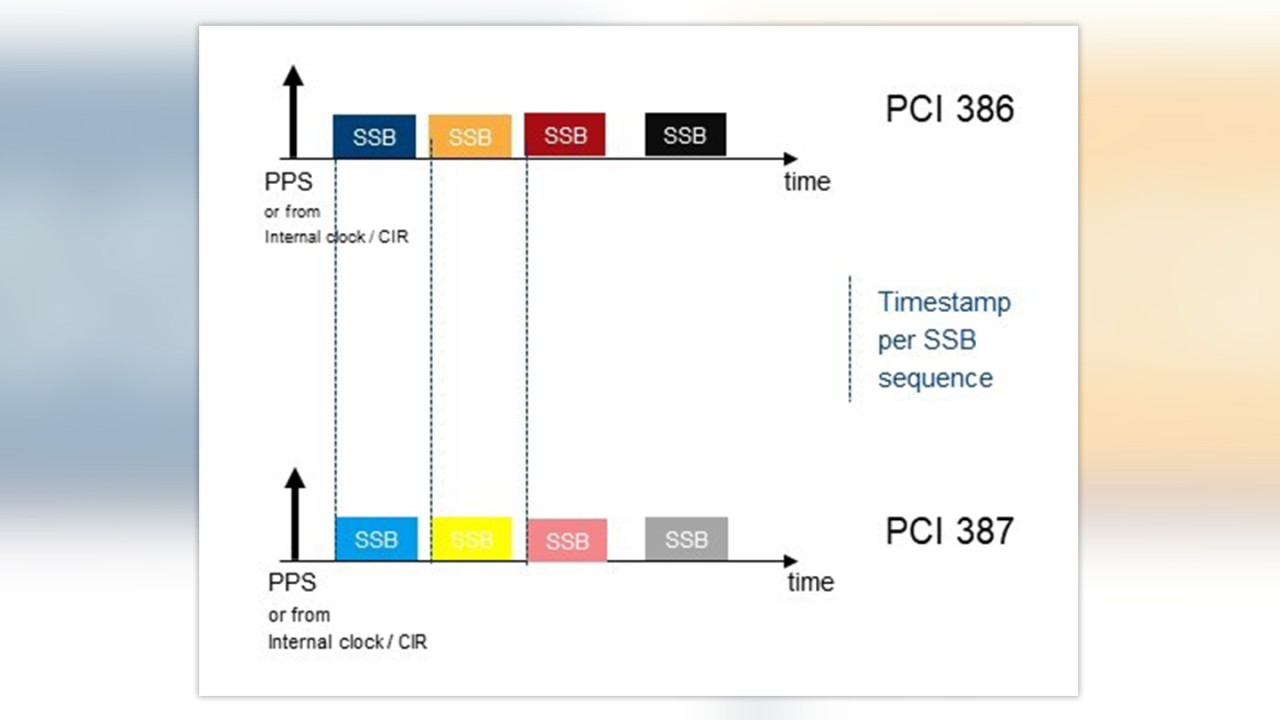
To verify the time synchronization of a network our scanner uses two possible measurements of varying precision: a time of arrival (ToA) measurement of the received SSBs and a time alignment error (TAE) measurement of the received SSBs. The ToA measurement provides a timestamp for the received SSB. This provides a good indication if a certain base station cell is out-of-sync compared to other base stations received. The ToA measurement provides a precision of about 400ns. The ToA measurement can be done for many cells simultaneously during a drive test.
In order to achieve higher precision and fulfill the Coordinated Universal Time (UTC) second synchronicity requirement, a so called TAE measurement is used. The TAE measurement can be done only for one cell and it requires a non-moving scanner in order to avoid Doppler shift and in order to allow more time-averaging. For the TAE measurement, a line of sight (LoS) to the cell is required where the distance between measurement antenna and cell antenna is known (this can be measured with a laser rangefinder) together with good GPS reception (or an external time base) as the time reference.
The receiver/scanner can calculate the UTC transmission time of every received SSB as well as the frequency error of the cell (as illustrated in Figure 2). The measurement precision is then dependent on the provided reference of the integrated GNSS receiver (good GPS reception results in a time accuracy below 30ns). Due to the known distance between measurement position and base station the transmit time can be calculated. This allows the investigation of timing issues rooted in the setup of the base station.
We verified experimentally that the following conditions need to be fulfilled to allow such a precise measurement:


This article post addressed a new application of synchronization signal (SS)/ physical broadcast channel (PBCH) blocks (or SSBs) broadcasted from 5G NR base stations in order to address the challenge of measurement of base station and network synchronization for TDD 5G networks. In the next blog post, we will address the controversial topic of how to measure the electromagnetic field (EMF) from base stations as EMF levels beyond country-specific thresholds could have potential health impacts (in particular frequencies above 3 GHz).
Learn more about 5G site acceptance scenarios, KPIs, test techniques, and field measurement results and watch the on-demand Webinar “5G Site Testing including latest real world challenges”.
[1] 3GPP technical specification TS 38.104, NR; Base Station (BS) radio transmission and reception, V17.7.0, Sep 2022
[2] 3GPP technical specification TS 38.133, NR; Requirements for support of radio resource management, V17.7.0, Oct 2022
[3] S. Rufini, M. Johansson, B. Pohlman and M. Sandgren, 5G Synchronization Requirements And Solutions, Ericsson Technology Review, Jan 2021
[4] GSMA, 5G TDD Synchronization – Guidelines and Recommendations for the Coexistence of TDD Networks in the 3.5 GHz Range, Apr 2020
[5] 3GPP technical specification TS 38.331, NR; Radio Resource Control (RRC) protocol specification, V16.3.0, Jan 2021
Read more about "5G mobile network testing using a passive scanner" part 1 - 3 of this series:
5G mobile network testing using a passive scanner (part 1)
5G mobile network testing using a passive scanner (part 2)
5G mobile network testing using a passive scanner (part 3)